
Electric connector in vacuum high-temperature environment

A high-temperature environment, electrical connector technology, applied in the direction of connection, connecting device components, circuits, etc., can solve problems such as unfavorable replacement and maintenance, inconvenient operation, and no insulation protection measures.

Active Publication Date: 2019-04-26
ENN SCI & TECH DEV
View PDF5 Cites 0 Cited by
  • Summary
  • Abstract
  • Description
  • Claims
  • Application Information

AI Technical Summary

Problems solved by technology

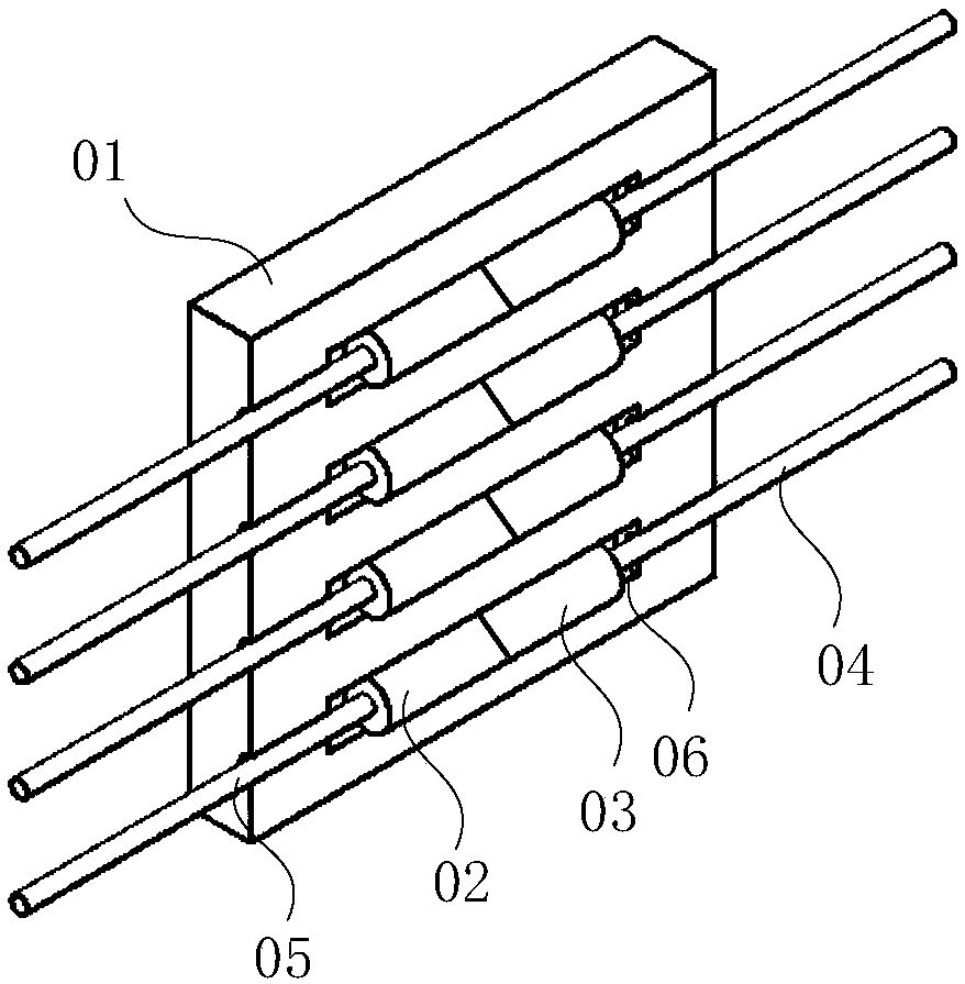
[0004] In the process of realizing the above-mentioned connection of electrical lines, the inventor found that the existing technical solutions have at least the following problems: first, after the lines are pressed and connected by cold-press connection, if you want to disconnect the connection, you can only cut the electrical lines. , the connector needs to be connected by cold pressure again, which is not conducive to replacement and maintenance, and there is no insulation protection measure; the second connection method, when the line connector needs to be connected or disconnected, the insulating plate with the groove needs to be removed first , and then carry out the plugging and unplugging of the first cold-pressed plug 02 and the second cold-pressed plug 03, the operation is very inconvenient, and the line connector cannot be plugged and unplugged at any time, which is not conducive to the replacement and maintenance of related equipment; and, in a high-temperature vacuum environment, the first The first cold-pressed plug 02 and the second cold-pressed plug 03 are easily fused with each other, making it impossible to separate

Method used


Image

  • Electric connector in vacuum high-temperature environment
  • Electric connector in vacuum high-temperature environment
  • Electric connector in vacuum high-temperature environment

Examples


Embodiment Construction

[0028] The following will clearly and completely describe the technical solutions in the embodiments of the present invention with reference to the accompanying drawings in the embodiments of the present invention. Obviously, the described embodiments are only some, not all, embodiments of the present invention. Based on the embodiments of the present invention, all other embodiments obtained by persons of ordinary skill in the art without making creative efforts belong to the protection scope of the present invention.

[0029] In describing the present invention, it is to be understood that the terms "upper", "lower", "left", "right", "vertical", "horizontal", "top", "bottom", "inner", The orientation or positional relationship indicated by "outside" is based on the orientation or positional relationship shown in the drawings, and is only for the convenience of describing the present invention and simplifying the description, rather than indicating or implying that the referre...


PUM


Abstract

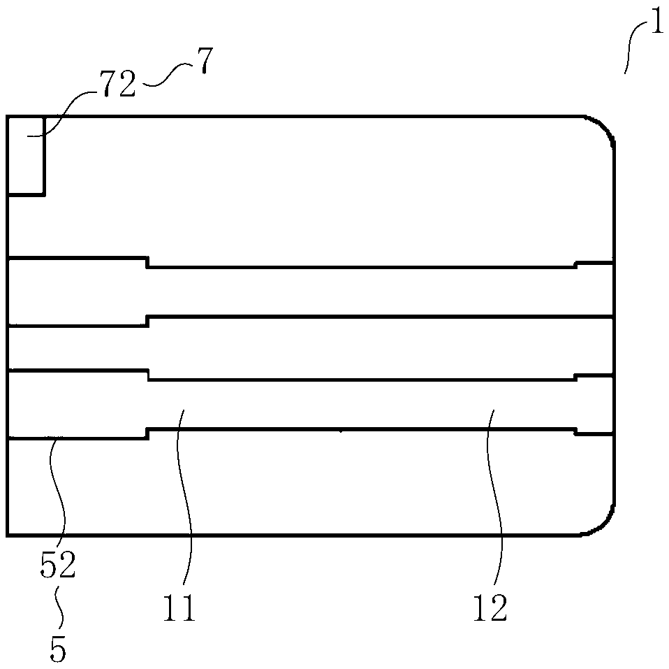
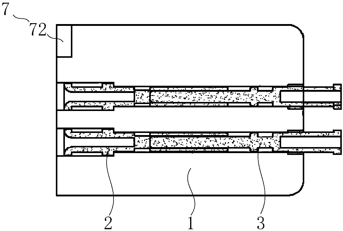
The invention discloses an electric connector in a vacuum high-temperature environment, and relates to the technical field of electric connectors. The plug of the electric connector can be plugged inand unplugged at any time under a vacuum environment and will not be fused, so that the equipment can be exchanged and maintained. The electric connector in a vacuum high-temperature environment comprises a plug base, wherein a first connecting hole and a second connecting hole are arranged on the plug base; the first connecting hole and the second connecting hole are communicated inside the plugbase; a first plug is fixed in the first connecting hole; a second plug is arranged in the second connecting hole and can be moved along the axial direction of the second connecting hole so that the first plug and the second plug are contacted or separated. The outer surface of the first plug is covered with a first anti-melting material layer, the outer surface of the second plug is covered witha second anti-melting material layer, and the melting points of the first anti-melting material layer and the second anti-melting material layer are different. The electrical connector in the vacuum high-temperature environment is used to connect or disconnect electrical lines.

Description

technical field [0001] The invention relates to the technical field of electrical connectors, in particular to an electrical connector in a vacuum and high temperature environment. Background technique [0002] Fusion reaction is a very important research direction in the utilization of nuclear energy. Fusion reaction refers to the reaction of mutual polymerization of atomic nuclei in the fusion reaction device under the conditions of ultra-high temperature, high vacuum and strong magnetic field. In the process of research and application, we need to detect and control the state of the fusion reaction in the fusion device in real time, and in the process of detecting and controlling the fusion reaction, we will use electrical lines to transmit electrical signals. In the process of connecting electrical lines It is often necessary to connect the line joints of different equipment. Generally, electrical connectors are used to realize the connection or signal transfer of the jo...

Claims


Application Information

Patent Timeline
Patent Type & Authority Applications(China)
IPC IPC(8): H01R13/533H01R13/03H01R13/42
CPCH01R13/03H01R13/42H01R13/533
Inventor 陶仁义郭栋刘敏胜
Owner ENN SCI & TECH DEV
Learn More