Production method for device temperature control device and filling method for working fluid

A technology for temperature adjustment devices and working fluids, which can be used in lighting and heating equipment, refrigerators, refrigeration and liquefaction, etc., and can solve problems such as unoptimized containers and heating

Inactive Publication Date: 2019-04-26
DENSO CORP
View PDF8 Cites 2 Cited by
  • Summary
  • Abstract
  • Description
  • Claims
  • Application Information

AI Technical Summary

Problems solved by technology

However, when considering the convenience of market service, it is not preferable to use a special pressurizing device
In addition, it is not preferable to heat the container from the viewpoint of safety because there is a risk of rupture of the container and the risk of a jetting accident of the working fluid.
[0015] In addition, such a problem also arises in an equipment temperature control device that is installed in a place other than a vehicle or that adjusts the temperature of equipment other than a battery.
In addition, such a problem also occurs in an equipment temperature control device having a circuit of a working fluid that constitutes a non-annular thermosiphon heat pipe.

Method used


Image

  • Production method for device temperature control device and filling method for working fluid
  • Production method for device temperature control device and filling method for working fluid
  • Production method for device temperature control device and filling method for working fluid

Examples


no. 1 approach

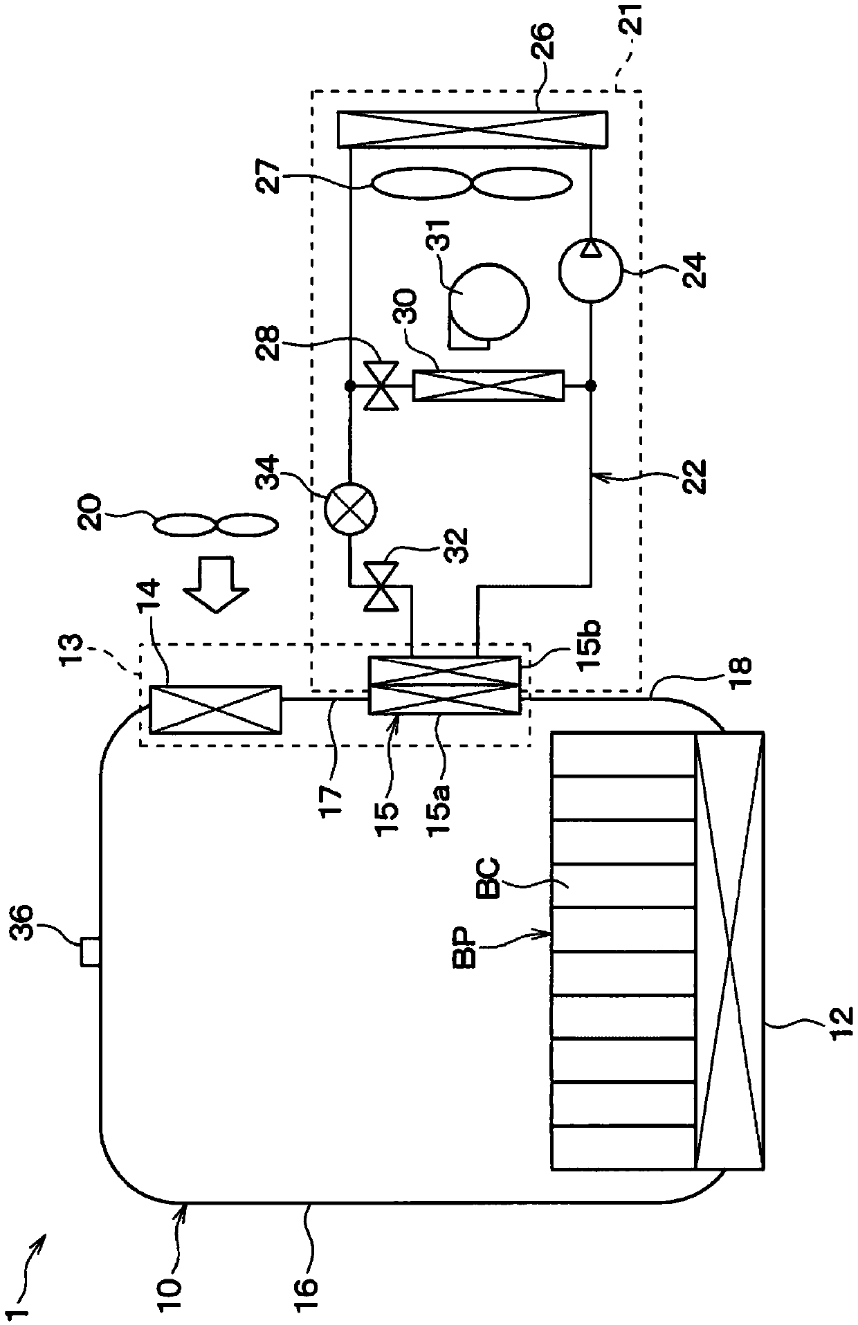
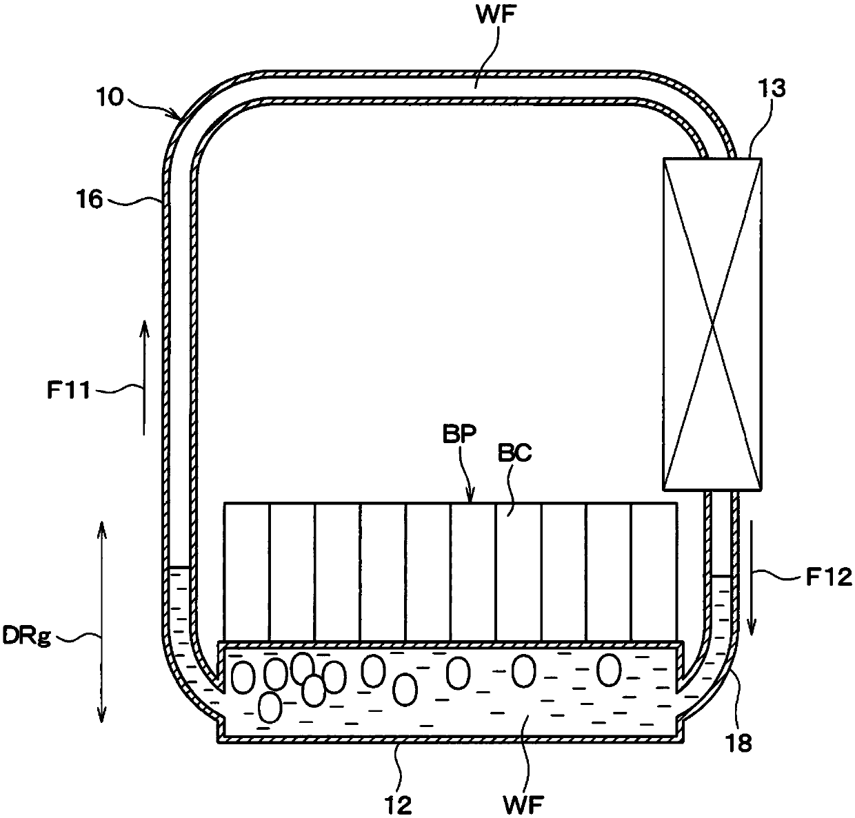
[0054] figure 1 The device temperature adjustment device 1 of the illustrated embodiment cools the battery pack BP mounted on the vehicle to adjust the battery temperature of the battery pack BP as the temperature adjustment target device. As a vehicle equipped with the equipment temperature control device 1, an electric vehicle or a hybrid vehicle that uses the battery pack BP as a power source and can be driven by a traveling motor (not shown) is assumed.

[0055] The battery pack BP is composed of a laminate in which a plurality of rectangular parallelepiped battery cells BC are stacked. The plurality of battery cells BC constituting the battery pack BP are electrically connected in series. Each battery cell BC constituting the battery pack BP is constituted by a secondary battery (for example, a lithium ion battery, a lead battery) that can be charged and discharged. In addition, the battery cell BC is not limited to a rectangular parallelepiped shape, and may have other sha...

no. 2 approach

[0110] Such as Figure 8 As shown, the condensing unit 13 for equipment in this embodiment is different from the first embodiment. The other structure of the device temperature adjustment device 1 is the same as that of the first embodiment.

[0111] The facility temperature control device 1 includes an air-cooled condenser 14 as the condensing unit 13 for facilities. The condenser 14 is a heat exchanger that exchanges heat between the working fluid and the blowing air blown to the condenser 14. The condenser 14 is selectively blown with external air and cold air lower than the external air as blowing air. The cold air is generated by the refrigeration cycle device 21. The cold air is cooling air that cools the working fluid.

[0112] Specifically, the facility temperature adjustment device 1 includes a switching device 51 that selectively switches between outside air and cold air as the blowing air to be blown to the condenser 14. The switching device 51 includes a duct 511 th...

no. 3 approach

[0122] Such as Picture 9 As shown, the condensing unit 13 for equipment of this embodiment is different from the first embodiment. The other structure of the device temperature adjustment device 1 is the same as that of the first embodiment.

[0123] The facility temperature control device 1 includes a water-cooled condenser 61 as the facility condensing unit 13 and a cooling water circuit 62 that circulates cooling water. Cooling water is a cooling liquid containing water. Coolant is a liquid heat medium used to transport heat. For example, use antifreeze, water, etc. as cooling water. The condenser 61 is a heat exchanger that condenses the working medium of the equipment fluid circuit 10 by performing heat exchange between the working medium and the cooling water of the cooling water circuit 62. The condenser 61 has a working fluid side heat exchange part 61 a through which the working fluid of the equipment fluid circuit 10 flows, and a cooling water side heat exchange par...


PUM


Abstract

A production method for a device temperature control device, including: connecting a filling port (36) for a circuit (10) and a container (45) housing a working fluid in a gas phase; and filling the working fluid into the circuit (10). The circuit (10) constitutes a thermosiphon-type heat pipe and circulates the working fluid. During filling, the working fluid inside the circuit (10) is cooled bya cooling source (21). The internal pressure of the circuit (10) is made lower than the internal pressure of the container (45), by reducing the internal temperature of the circuit (10) to below the internal temperature of the container (45).

Description

[0001] Cross-reference of related applications [0002] This application is based on the Japanese Patent Application No. 2016-176791 filed on September 9, 2016, and the content of the description is incorporated herein by reference. Technical field [0003] The invention relates to a method for manufacturing an equipment temperature adjustment device for adjusting the temperature of the equipment. Background technique [0004] Patent Document 1 discloses a temperature adjustment device that adjusts the temperature of a battery mounted on a vehicle. The temperature adjustment device is provided with a circuit of a working fluid, and the circuit of the working fluid constitutes a ring-shaped thermosyphon heat pipe. This circuit has an evaporation part in which the working fluid evaporates by absorbing heat from the battery, and a condensing part in which the working fluid evaporated in the evaporation part is cooled and condensed. [0005] Prior art literature [0006] Patent literatur...

Claims


Application Information

Patent Timeline
Patent Type & Authority Applications(China)
IPC IPC(8): F28D15/02F25B1/00H05K7/20
CPCF25B1/00F28D15/02H05K7/20F25B23/006F28D15/0266F25B45/00F28D15/06H05K7/2029H01L23/427F28D15/043B23P15/26B23P2700/09F28D15/0283
Inventor 大见康光山中隆加藤吉毅义则毅竹内雅之三浦功嗣
Owner DENSO CORP
Why Eureka
Try Eureka