Method for manufacturing sintered body for forming sintered magnet, and method for manufacturing permanent magnet using sintered body for forming sintered magnet

A technology for sintered magnets and manufacturing methods, which is applied in the manufacture of stator/rotor bodies, magnetic circuits featuring magnetic materials, and inductance/transformer/magnet manufacturing, etc. The effect of improving, preventing breakage, and improving followability

Active Publication Date: 2019-04-26
NITTO DENKO CORP
View PDF7 Cites 0 Cited by
  • Summary
  • Abstract
  • Description
  • Claims
  • Application Information

AI Technical Summary

Problems solved by technology

On the other hand, if the pressure is applied at a low pressure, there is a problem that the followability to the sintered mold cannot be sufficiently improved.

Method used


Image

  • Method for manufacturing sintered body for forming sintered magnet, and method for manufacturing permanent magnet using sintered body for forming sintered magnet
  • Method for manufacturing sintered body for forming sintered magnet, and method for manufacturing permanent magnet using sintered body for forming sintered magnet
  • Method for manufacturing sintered body for forming sintered magnet, and method for manufacturing permanent magnet using sintered body for forming sintered magnet

Examples


Embodiment 1

[0092]

[0093] Alloys having an alloy composition A shown in Table 1 below and obtained by a strip casting method were allowed to store hydrogen at room temperature and kept at 0.85 MPa for 1 day. Then, hydrogen fragmentation was performed by maintaining at 0.2 MPa for 1 day while cooling with liquid argon (Ar).

[0094] [Table 1]

[0095]

[0096]

[0097] With respect to 100 parts by weight of the alloy coarse powder pulverized by hydrogen, 1.5 kg of Zr beads (2mmφ) were mixed, and put into a ball mill with a tank capacity of 0.8 L (product name: ATTRITOR 0.8 L, manufactured by Nippon Coke Industry Co., Ltd.), at a rotation speed of 500 rpm Crush for 2 hours. As a grinding aid at the time of grinding, 10 parts by weight of benzene was added, and liquid argon (Ar) was used as a solvent. The particle size after pulverization is about 1 μm.

[0098]

[0099] With respect to 100 parts by weight of the pulverized alloy particles, the binder and the orientation lubric...

Embodiment 2~10、 comparative example 1~3

[0117] Under the conditions described in Table 3, basically the same operation as in Example 1 was performed to obtain each sintered body. Details of steps not described in Example 1 are shown below.

[0118]

[0119] The jet mill pulverization was performed as follows. 1 part by weight of methyl hexanoate was mixed with 100 parts by weight of the hydrogen-pulverized coarse alloy powder, and then pulverized by a helium jet mill pulverizer (device name: PJM-80HE, manufactured by NPK). The collection of pulverized alloy particles is separated and recovered by means of a cyclone separator, and the ultrafine powder is removed. Set the supply rate during pulverization to 1kg / h, the introduction pressure of He gas to 0.6MPa, and the flow rate to 1.3m 3 / min, the oxygen concentration is below 1ppm, and the dew point is below -75°C. The particle size after pulverization is about 1 μm.

[0120]

[0121] Add 40 parts by weight of 1-octene to 100 parts by weight of finely pulveri...


PUM

PropertyMeasurementUnit
particle sizeaaaaaaaaaa
particle diameteraaaaaaaaaa
densityaaaaaaaaaa

Abstract

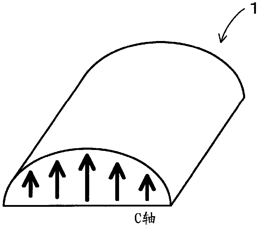
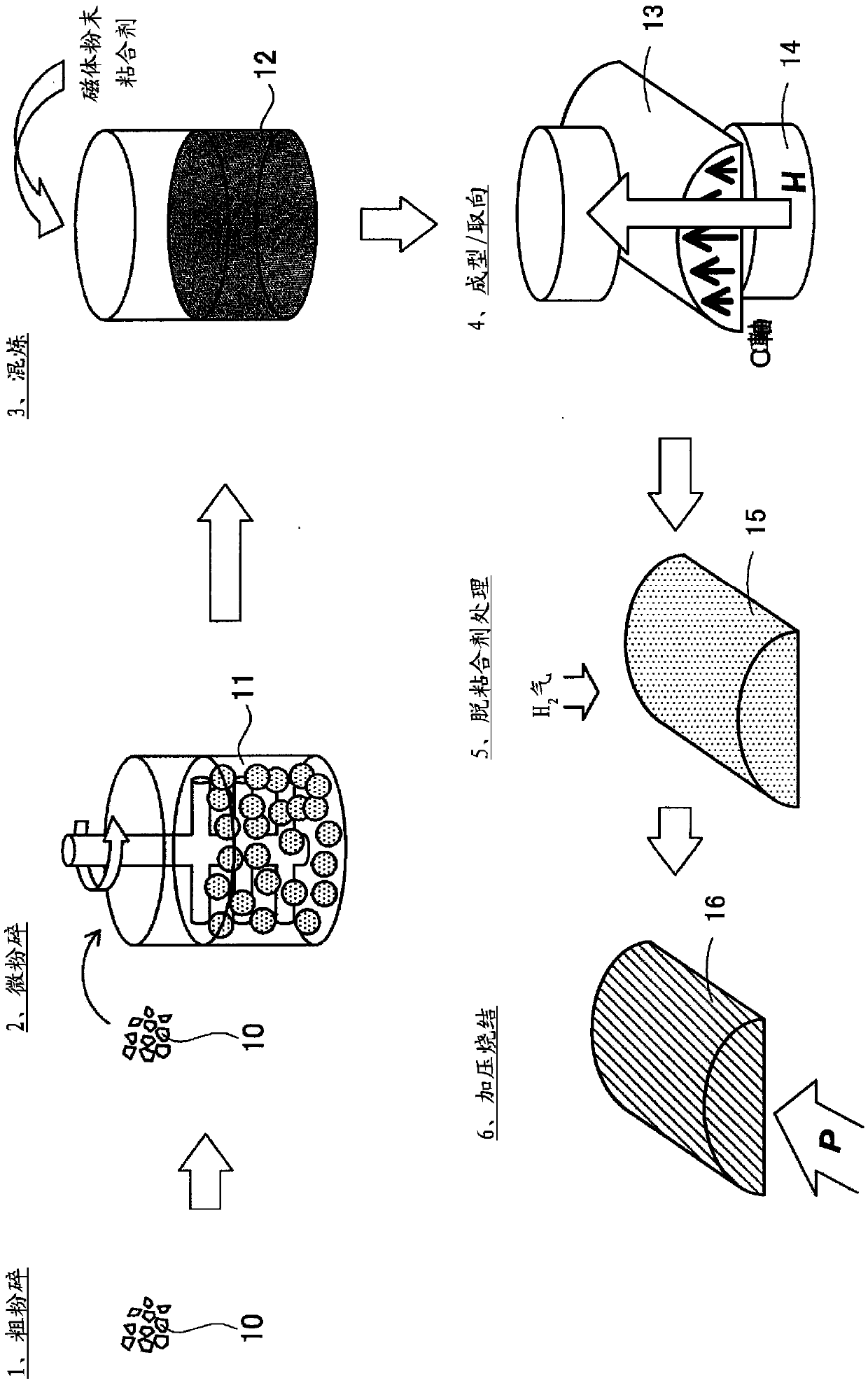
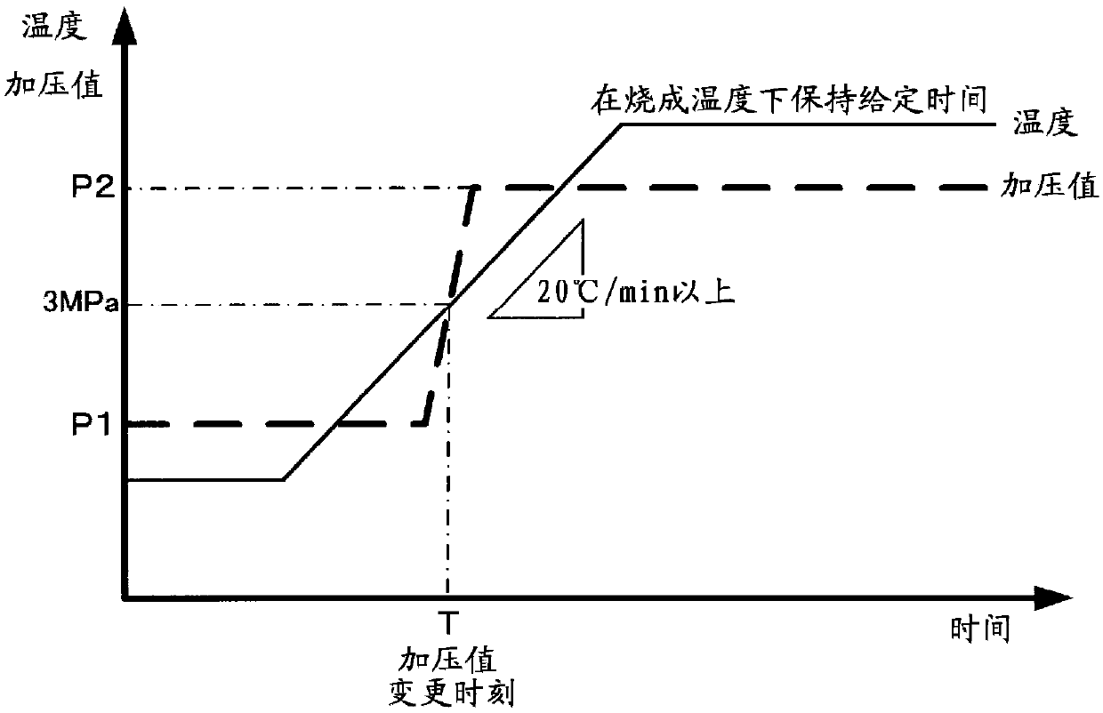
Provided is a method for manufacturing a sintered body for forming a sintered magnet, the method improving conformity to a sintering mold during sintering and also preventing the development of cracksin a molded body. A method for manufacturing a permanent magnet is also provided. Specifically, a magnet raw material is pulverized into magnet powder, and the magnet powder obtained by the pulverization is mixed with a binder to produce a compound 12. The compound 12 is molded into a molded body 13 which is heated to a firing temperature under pressure at a predetermined temperature increase rate, and is sintered while being retained at the firing temperature. In the sintering step, after the start of the temperature increase in the molded body 13 and until a predetermined timing during thetemperature increase in the molded body 13, the pressurization value for pressurizing the molded body 13 is set to less than 3 MPa, and to not less than 3 MPa after the timing.

Description

technical field [0001] The present invention relates to a method for manufacturing a sintered body for forming a sintered magnet, and a method for manufacturing a permanent magnet using the sintered body for forming a sintered magnet. Background technique [0002] In recent years, reduction in size and weight, higher output, and higher efficiency are required for permanent magnet motors used in hybrid vehicles, hard disk drives, and the like. Therefore, in order to reduce the size, weight, output, and efficiency of the above-mentioned permanent magnet motor, it is required to reduce the thickness of the permanent magnet embedded in the motor and to further improve the magnetic properties. [0003] Among them, as a method of manufacturing a permanent magnet used in a permanent magnet motor, that is, a sintered magnet, a powder sintering method has conventionally been generally used. Here, in the powder sintering method, firstly, a magnet powder obtained by pulverizing a raw ...

Claims


Application Information

Patent Timeline
Patent Type & Authority Applications(China)
IPC IPC(8): H01F41/02B22F3/00B22F3/02B22F3/10C22C38/00H01F1/057H02K15/03
CPCC22C38/00C22C38/005C22C38/12C22C38/10C22C38/06C22C38/002C22C38/16B22F2998/10B22F2999/00B22F3/14H01F1/0577H01F41/0273B22F3/02B22F2003/023B22F2003/145B22F9/04B22F2009/043B22F2009/044B22F2202/05B22F3/12H01F1/057H01F1/06H01F41/0266H02K15/03C22C2202/02H01F1/086H02K1/02B22F3/15B22F2301/355B22F3/00H01F41/02B22F3/10
Inventor 江部宏史尾关出光山本贵士藤川宪一
Owner NITTO DENKO CORP
Why Eureka
Try Eureka