
Device for automatically feeding material into stamping die

A technology of automatic feeding and stamping dies, which is applied in the field of cold stamping dies, can solve the problems of affecting feeding accuracy, mold damage, material tape arching, etc., and achieves the effect of low cost, simple structure and easy processing

Inactive Publication Date: 2019-04-30
厦门捷昕精密科技股份有限公司
View PDF5 Cites 0 Cited by
  • Summary
  • Abstract
  • Description
  • Claims
  • Application Information

AI Technical Summary

Problems solved by technology

[0002] Stamping die is a special process equipment for processing materials (metal or non-metal) into parts (or semi-finished products) in cold stamping processing. The feeding of the traditional stamping processing strip process must be completed by configuring peripheral feeders, and in There are still certain problems in the realization of ultra-thin material thickness products: when the ultra-thin material thickness products realize multi-station, the strength of the material belt is not good, relying on the feeding method of the feeder in the front part of the mold is prone to arching of the material belt, which affects the accuracy of feeding , easy to cause damage to the mold

Method used


Image

  • Device for automatically feeding material into stamping die
  • Device for automatically feeding material into stamping die
  • Device for automatically feeding material into stamping die

Examples


Embodiment Construction

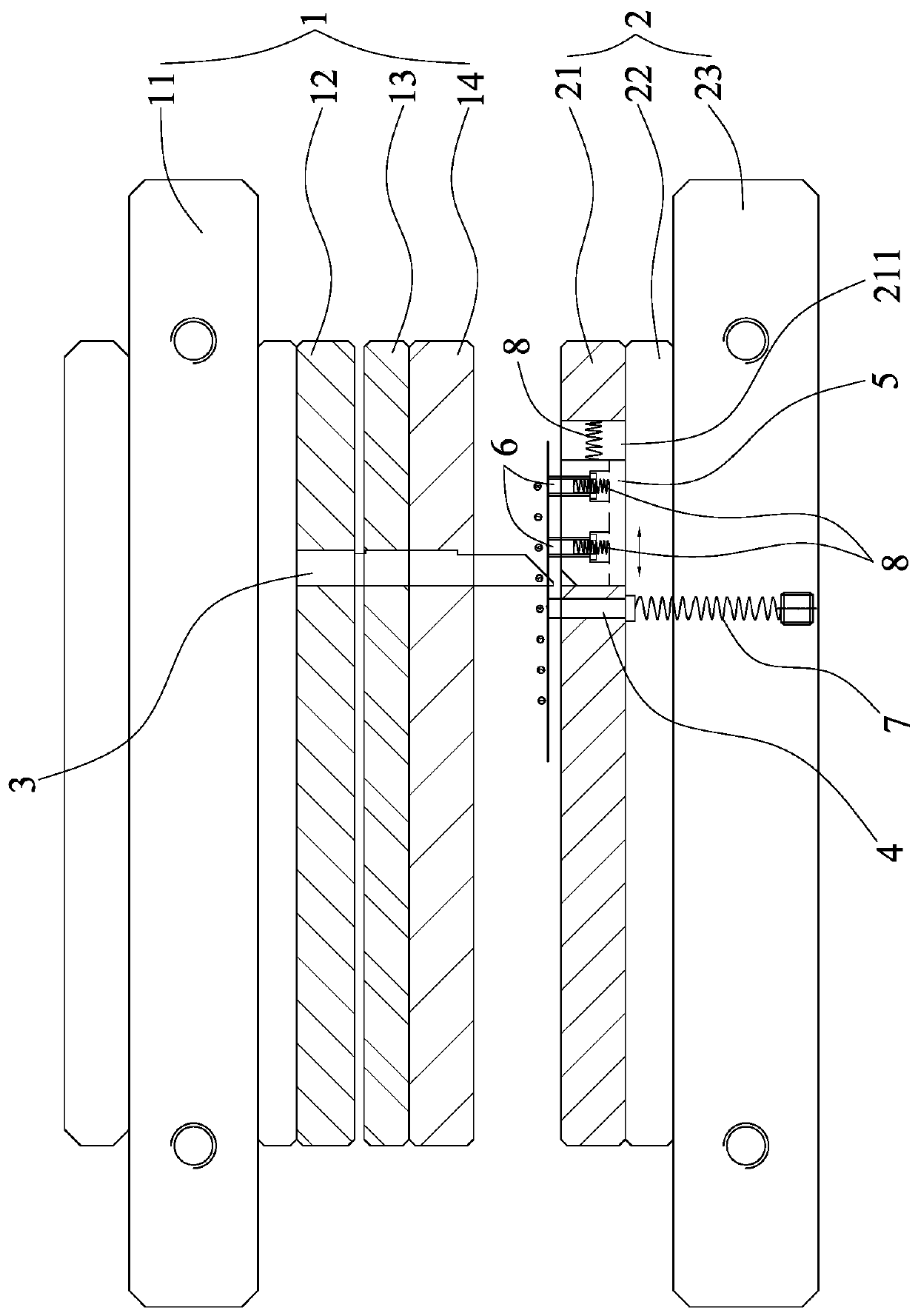
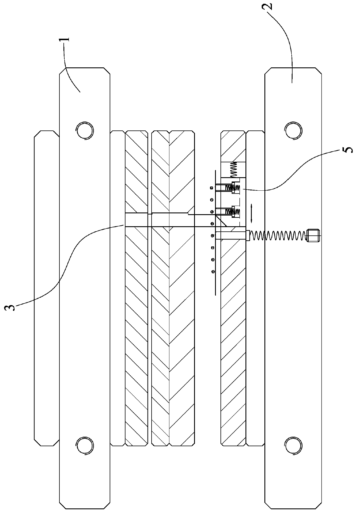
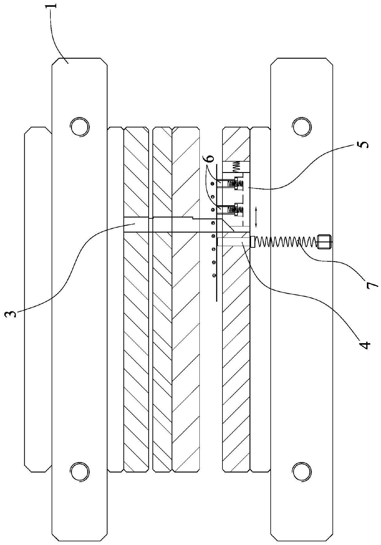
[0021] Such as figure 1 As shown, the present invention is an automatic feeding device in a stamping die, including an upper die 1, a lower die 2, a driving punch 3, a stop pin 4, a slider 5, a feed pin 6, a stop pin lift spring 7, and a feed pin Lifting spring 8, back-moving spring 9.

[0022] The upper mold 1 and the lower mold 2 are arranged oppositely. Described patrix 1 comprises patrix 11, upper splint 12, stripping backing plate 13, stripping plate 14; Described patrix 11 and splint 12 are fixed together, stripping pad 13 and stripping Plates 14 are secured together and overlapped with upper splint 12 . The lower mold 2 includes a lower template 21, a lower backing plate 22 and a lower mold base 23; the lower template 21, the lower backing plate 22 and the lower mold base 23 are sequentially fixed and stacked together.

[0023] The upper end of the driving punch 3 is installed on the upper splint 12 of the upper die 1, the lower end of the driving punch has an inclin...


PUM


Abstract

The invention discloses a device for automatically feeding a material into a stamping die. The device comprises a driving stamper, a stop pin, a sliding block, a feeding pin, a stop pin floating spring and a feeding pin floating spring; the upper end of the driving stamper is arranged on an upper die, the sliding block is slidably arranged in a lower die, an inclined surface of the sliding block is opposite to and can abut against an inclined surface at the lower end of the driving stamper, the lower end of the stop pin is movably sleeved with the lower die, the lower end of the stop pin abutsagainst the stop pin floating spring, the stop pin floating spring is sleeved with the lower die, the lower end of the feeding pin is movably sleeved with the sliding block, the lower end of the feeding pin abuts against the feeding pin floating spring, and the feeding pin floating spring is sleeved with the sliding block. According to the device, a material guide block composed of the sliding block and the feeding pin is used for pulling the material in the feeding-in direction, the stop pin is used for limiting a material belt to retreat during restoring, due to adoption of the internal material pulling structure of the device, the problem that the material belt is arched is well solved, and the device has the advantages of being low in cost, simple in structure and easy to machine.

Description

technical field [0001] The invention relates to a cold stamping die, in particular to an automatic feeding device in the stamping die. Background technique [0002] Stamping die is a special process equipment for processing materials (metal or non-metal) into parts (or semi-finished products) in cold stamping processing. The feeding of the traditional stamping processing strip process must be completed by configuring peripheral feeders, and in There are still certain problems in the realization of ultra-thin material thickness products: when the ultra-thin material thickness products realize multi-station, the strength of the material belt is not good, relying on the feeding method of the feeder in the front part of the mold is prone to arching of the material belt, which affects the accuracy of feeding , easy to cause damage to the mold. Contents of the invention [0003] The object of the present invention is to provide an automatic feeding device in the stamping die wi...

Claims


Application Information

Patent Timeline
Patent Type & Authority Applications(China)
IPC IPC(8): B21D37/10B21D43/02
CPCB21D37/10B21D43/02
Inventor 张泽鹏
Owner 厦门捷昕精密科技股份有限公司
Learn More