
Projection lamp with automatic reciprocating capability for stage

An automatic reciprocating and projection lamp technology, applied in lighting applications, components of lighting devices, and loss prevention measures of lighting devices, etc. Shock absorption effect, the effect of reducing the failure rate

Inactive Publication Date: 2019-04-30
UNIV OF ELECTRONICS SCI & TECH OF CHINA ZHONGSHAN INST
View PDF0 Cites 2 Cited by
  • Summary
  • Abstract
  • Description
  • Claims
  • Application Information

AI Technical Summary

Problems solved by technology

[0005] However, most of the projection lights used on the stage need to be swayed to make the light shake and produce a more cool stage effect. At present, most of the existing stage projection lights need to be manually controlled to achieve the swing function, and the automatic rotation effect is not good. needs to be improved

Method used


Image

  • Projection lamp with automatic reciprocating capability for stage
  • Projection lamp with automatic reciprocating capability for stage
  • Projection lamp with automatic reciprocating capability for stage

Examples


Embodiment 1

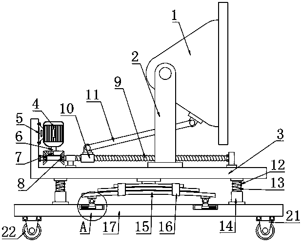
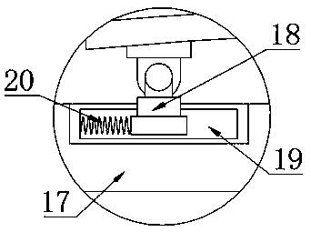
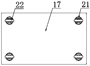
[0026] see Figure 1-4 , a stage projection lamp that can automatically reciprocate and swing, including a lamp body 1, a cage 3, a threaded rod 9, a leaf spring 15, a bottom plate 17, and a moving wheel 22; The lower end of the support rod 2 is fixedly connected to the cage 3, and the tail of the cage 3 is provided with a drive motor 4, the drive motor 4 is fixedly connected to the motor base 5, the motor base 5 is fixedly connected to the cage 3 by bolts, and the lower part of the drive motor 4 is connected to the driving shaft in rotation 6. It should be noted that the wires of the driving motor 4 are connected to the power supply and the switch, and pressing the switch makes the driving motor 4 energized to drive the driving shaft 6 to rotate; the lower end of the driving shaft 6 is fixedly connected to the semi-conical gear 7, and half of the semi-conical gear 7 has Half of the teeth have no teeth, and the two sides of the half bevel gear 7 are respectively provided with ...

Embodiment 2

[0030] see Figure 1-4 , a stage projection lamp that can automatically reciprocate and swing, including a lamp body 1, a cage 3, a threaded rod 9, a leaf spring 15, a bottom plate 17, and a moving wheel 22; The lower end of the support rod 2 is slidingly connected to the cylinder, the lower end of the cylinder is fixedly connected to the cage 3, the signal of the cylinder is connected to the switch and the power supply, and the tail of the cage 3 is provided with a driving motor 4, and the driving motor 4 is fixedly connected to the motor base 5, and the motor base 5 is fixed by bolts Connect the cage 3, the drive shaft 6 is connected to the lower part of the drive motor 4. It should be noted that the drive motor 4 leads are connected to the power supply and the switch, and the switch is pressed so that the drive motor 4 is energized to drive the drive shaft 6 to rotate; the lower end of the drive shaft 6 Fixedly connected to the semi-conical bevel gear 7, half of the semi-co...

Embodiment 3

[0034] see figure 1 , figure 2 and Figure 4 , a stage projection lamp that can automatically reciprocate and swing, including a lamp body 1, a cage 3, a threaded rod 9, a leaf spring 15, a bottom plate 17, and a moving wheel 22; The lower end of the support rod 2 is fixedly connected to the cage 3, and the tail of the cage 3 is provided with a drive motor 4, the drive motor 4 is fixedly connected to the motor base 5, the motor base 5 is fixedly connected to the cage 3 by bolts, and the lower part of the drive motor 4 is connected to the driving shaft in rotation 6. It should be noted that the wires of the driving motor 4 are connected to the power supply and the switch, and pressing the switch makes the driving motor 4 energized to drive the driving shaft 6 to rotate; the lower end of the driving shaft 6 is fixedly connected to the semi-conical gear 7, and half of the semi-conical gear 7 has Half of the teeth have no teeth, and the two sides of the half bevel gear 7 are re...


PUM


Abstract

The invention discloses a projection lamp with automatic reciprocating capability for a stage. The lower end of a driving shaft is fixedly connected with a semi-cone gear which has teeth on one half and has no teeth on the other half, and bevel gears are arranged on two sides of the semi-cone gear respectively and fixedly connected to the left side of a threaded rod; a ferrule is in threaded connection to the threaded rod, the upper part of the ferrule is rotationally connected with the lower end of a connecting rod, the upper end of the connecting rod is rotationally connected with the lowerpart of a lamp body, two sides of the lower end of a cage are fixedly connected with movable rods respectively, the lower parts of the movable rods are sleeved with sleeve seats, the movable rods arefurther sleeved with damping springs, the upper ends of the damping springs are in butt joint with the lower surface of the cage, and the lower ends of the damping springs are in butt joint with the sleeve seats. The toothed part of the semi-cone gear is meshed with the bevel gears back and forth to drive the threaded rod to rotate back and forth forwards and reversely, the threaded rod drives theferrule to drive the connecting rod to drive the lamp body to reciprocate around the upper end of a support rod, and elastic connection between the cage and a bottom plate is realized by the movablerods and the sleeve seats connected by the damping springs.

Description

technical field [0001] The invention relates to a lighting fixture, in particular to a projection lamp for a stage that can automatically reciprocate and swing. Background technique [0002] Projector lamps have been promoted and used more and more widely in recent years, including single buildings and exterior wall lighting of historical buildings. The interior and exterior lighting of the building, and indoor partial lighting. Green landscape lighting, billboard lighting. Medical, cultural and other special facilities lighting. Atmosphere lighting in bars, dance halls and other entertainment places. [0003] LED projection lamps are also called linear LED projection lamps, etc., because of their long strip shape, some people call them LED line lamps, which are mainly used for architectural decoration lighting, and are also used to outline the outline of large buildings. , its technical parameters are roughly similar to those of LED projection lamps. Compared with the c...

Claims


Application Information

Patent Timeline
Patent Type & Authority Applications(China)
IPC IPC(8): F21L4/00F21V15/04F21V21/06F21V21/14F21W131/406
CPCF21L4/00F21V15/04F21V21/06F21V21/14F21W2131/406
Inventor 宋喜佳
Owner UNIV OF ELECTRONICS SCI & TECH OF CHINA ZHONGSHAN INST
Learn More