Anti-flooding gate control cabinet

An anti-flooding door and control cabinet technology, applied in electrical program control, program control in sequence/logic controllers, door/window accessories, etc., can solve control failures, high stability requirements, and equipment component failures and other problems to achieve the effect of reducing the possibility of failure, improving reliability and safety

Pending Publication Date: 2019-05-03
湖南沄辉科技股份有限公司
View PDF0 Cites 2 Cited by
  • Summary
  • Abstract
  • Description
  • Claims
  • Application Information

AI Technical Summary

Problems solved by technology

[0003] The anti-flooding door is installed in the river crossing tunnel of the subway or other rail transit, and its control system must be linked with the subway control system. When the anti-flooding door is started to descend to block the tunnel, it must be ensured that no subway passes through the blocking area. The anti-flood door will only be activated in the event of a major accident. Therefore, the anti-flood door control system has high requirements for stability. If the conventional control cabinet is often idle, it may be affected by the external temperature and humidity. Component failures lead to control failures. At present, there is a lack of a control cabinet specially designed for rail transit anti-flooding door systems

Method used


Image

  • Anti-flooding gate control cabinet
  • Anti-flooding gate control cabinet
  • Anti-flooding gate control cabinet

Examples


Embodiment Construction

[0026] In order to describe the technical content, achieved goals and effects of the present invention in detail, the following will be described in combination with real-time methods and accompanying drawings.

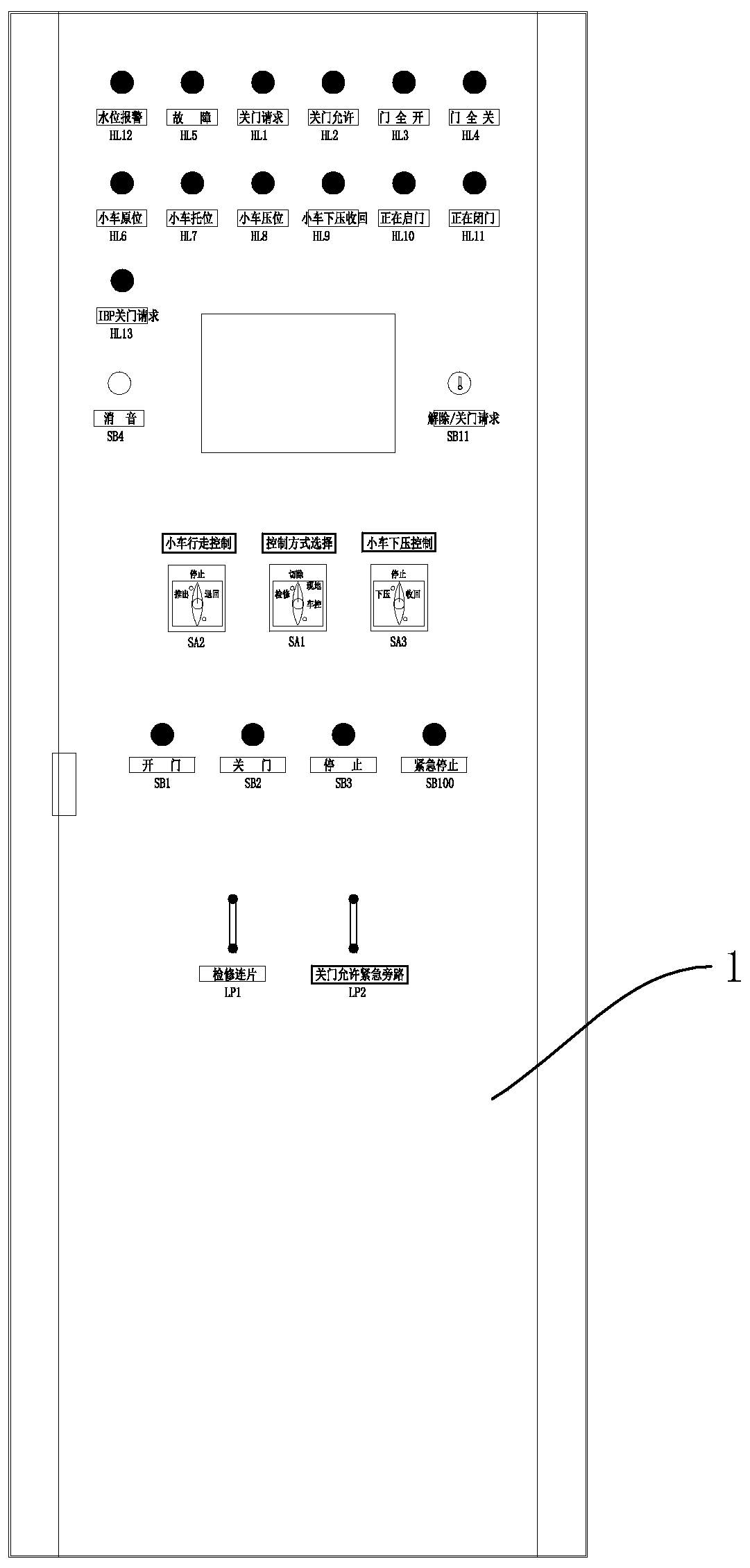
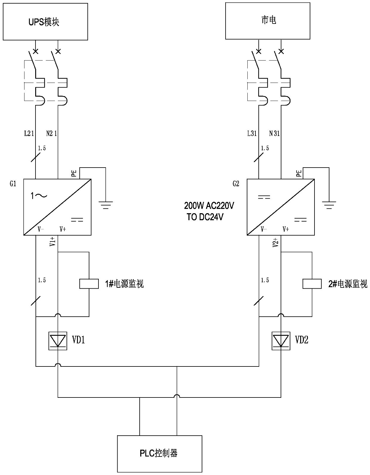
[0027] Such as Figure 1-Figure 5 Shown is an anti-flood door control cabinet of the present invention, the anti-flood door power system, including: a cabinet body 1, a power module 2 arranged in the cabinet body 1, a PLC controller 3, an ATC system interface 4, and a vehicle control room IBP Disk interface 5, conventional communication interface 6, anti-shelter door control module 7 and temperature and humidity control module 8.

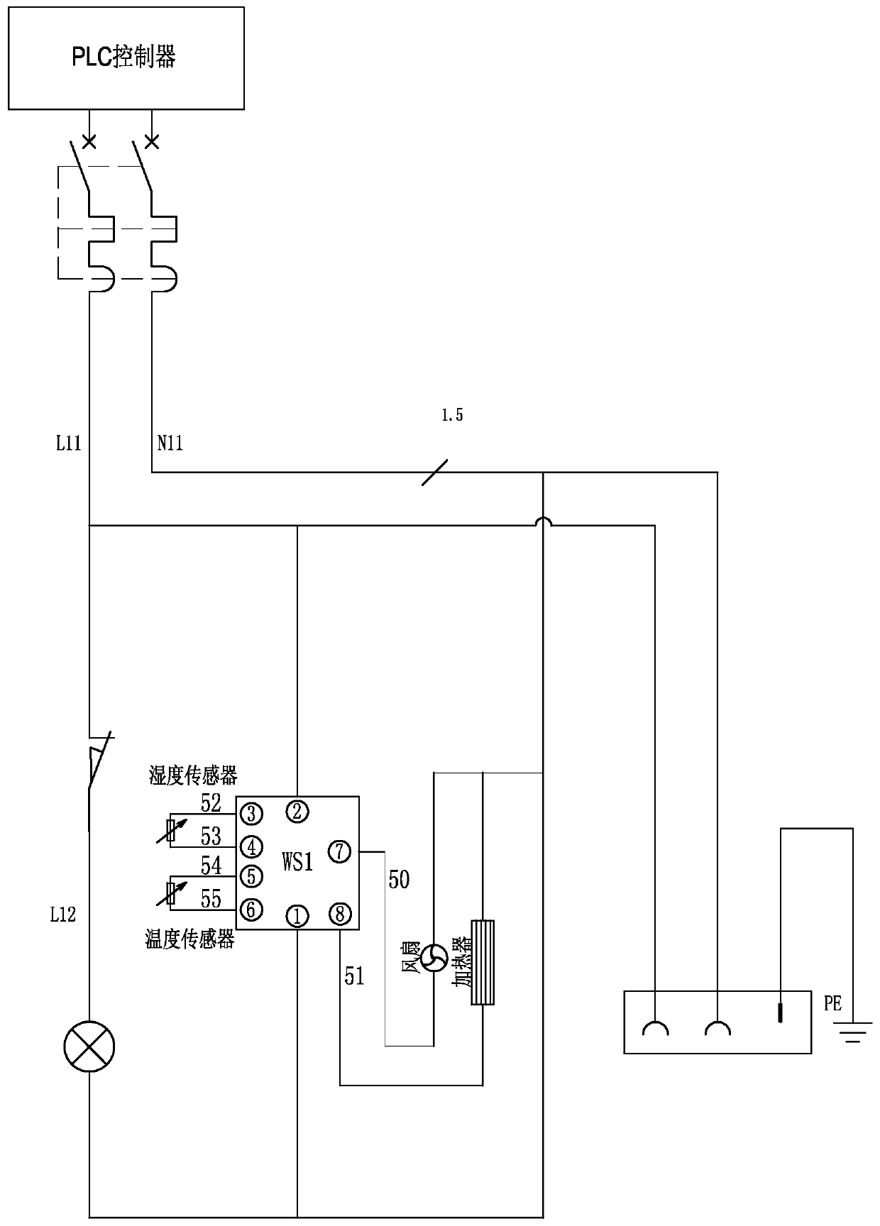
[0028] Such as figure 2 As shown, the temperature and humidity control module 8 includes a temperature sensor, a humidity sensor, a fan and a heater respectively connected to the PLC controller 3, and the temperature and humidity sensors are set in the cabinet, and the PLC controller 3 controls the fan and the heater simultaneously. oper...


PUM


Abstract

The invention discloses an anti-flooding gate control cabinet. The anti-flooding gate control cabinet comprises a cabinet body, a power supply module, a PLC, an ATC system interface, a vehicle controlroom IBP panel interface, a conventional communication interface, an anti-flooding gate control module and a temperature and humidity control module, wherein the power supply module, the PLC, the ATCsystem interface, the vehicle control room IBP panel interface, the conventional communication interface, the anti-flooding gate control module and the temperature and humidity control module are arranged in the cabinet body. The ATC system interface is connected with the PLC, and the vehicle control room IBP panel interface is connected with the PLC; the power supply module is connected with thePLC; the anti-flooding gate control module comprises a relay module and a door body state sensor, wherein the relay module and the door body state sensor are separately connected with the PLC; the temperature and humidity control module is connected with the PLC; and the conventional communication interface is connected with the PLC. According to the anti-flooding gate control cabinet, the linkage requirement of an anti-flooding gate and a subway system in an emergency state is met; in addition, the temperature and humidity in the cabinet body can be monitored and adjusted through the temperature and humidity control module, so that the devices in the cabinet body is always in a best working state; and the possibility of failure is reduced, and the reliability and safety are improved.

Description

technical field [0001] The invention relates to the field of anti-flood door control, in particular to an anti-flood door control cabinet. Background technique [0002] After more than ten years of construction, urban rail transit has formed a large scale, and the long-term planning of cities in various provinces even reaches 2050. Subway rail transit is mainly based on operation in normal times, and civil air defense is also taken into account during wartime. In order to meet the needs of subway civil air defense, the subways that pass through river tunnels are generally equipped with pure anti-flooding doors, and some are equipped with civil air defense partition doors. For example, in Guangzhou Metro, anti-flood doors and civil air defense partition doors are installed on the existing lines when they cross rivers. This way, the civil works take up a lot of space, difficult to arrange, and high in cost. Therefore, according to the development of the city, cost saving will...

Claims


Application Information

Patent Timeline
IPC IPC(8): E05F15/71E05F15/40G05B19/05
Inventor 李罗平
Owner 湖南沄辉科技股份有限公司
Why Eureka
Try Eureka