Vibrating compaction table

A technology of vibrating tables and benches, which is applied to casting molding equipment, metal processing equipment, molding machines, etc., can solve the problems of poor vibration effect of vibrating tables, poor sand compactness, and poor forming effects of lost foam, and achieves Improve the vibration amplitude and ingenious structural design

Pending Publication Date: 2019-05-07
姜海林 +1
View PDF0 Cites 2 Cited by
  • Summary
  • Abstract
  • Description
  • Claims
  • Application Information

AI Technical Summary

Problems solved by technology

The vibration effect of the vibrating table of this structure is poor, and the compactne

Method used


Image

  • Vibrating compaction table
  • Vibrating compaction table
  • Vibrating compaction table

Examples


Embodiment Construction

[0025] The following will clearly and completely describe the technical solutions in the embodiments of the present invention with reference to the accompanying drawings in the embodiments of the present invention. Obviously, the described embodiments are only some, not all, embodiments of the present invention. Based on the embodiments of the present invention, all other embodiments obtained by persons of ordinary skill in the art without making creative efforts belong to the protection scope of the present invention.

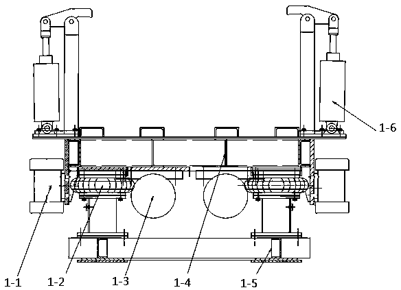
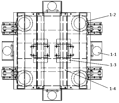
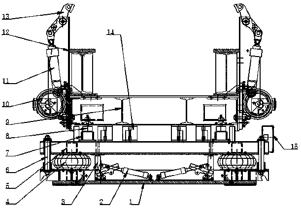
[0026] see Figure 3-4 , the present invention provides a vibrating table, comprising a base 1 and an intermediate frame 5 arranged above the base 1, a plurality of air springs 4 capable of raising or lowering the intermediate frame 5 are installed between the base 1 and the intermediate frame 5, and the middle The upper surface of the frame 5 is equipped with a plurality of spaced electromagnet disks 7 and a plurality of spacers 14 for shock absorption and su...


PUM


Abstract

The invention relates to a vibrating compaction table which is particularly suitable for vibrating compaction of dry sand, and belongs to the technical field of vibrating compaction table structures.The vibrating compaction table comprises a base and a middle frame arranged above the base, wherein a plurality of air springs capable of enabling the middle frame to ascend or descend are arranged between the base and the middle frame, and a plurality of electric magnetic discs which are separated at intervals and a plurality of cushion blocks with damping and supporting functions are installed on the upper surface of the middle frame; and a magnetized disc is correspondingly arranged above each electric magnetic disc, the magnetized discs are installed on the lower surface of an upper vibrating table frame, and a vibration motor and a clamping mechanism used for clamping a sand box are installed on the two opposite side walls of the upper vibration table frame. According to the vibratingcompaction table, the flowing direction of the dry sand can be automatically controlled according to actual needs, the vibration effect is good, the dry sand can meet the actually required compactness, the working efficiency is high, and energy saving and consumption reducing are achieved.

Description

technical field [0001] The invention relates to a vibrating table, which is especially suitable for dry sand compacting and belongs to the technical field of vibrating table structures. Background technique [0002] At present, the existing vibrating table includes a square body stand 1-4, the main vibration motor 1-3 is installed at the bottom of the square body stand 1-4, and a side vibrating motor 1-3 is installed on the four sides of the square body stand 1-4. Vibration motor 1-1, air spring 1-2 is installed on the lower surface of square body stand 1-4, the bottom of air spring 1-2 is fixed on the chassis 1-5, and the left and right sides of square body stand 1-4 lean on The upper position is equipped with a pneumatic clamping mechanism 1-6 for fixing the sand box. [0003] When working, the sand box is placed on the square body stand, the sand box is clamped by the pneumatic clamping mechanism, the air spring rises, the main motor 1-3 and the side motor 1-1 vibrate, t...

Claims


Application Information

Patent Timeline
IPC IPC(8): B22C15/14
Inventor 姜海林谢沛文
Owner 姜海林
Why Eureka
Try Eureka