A laminar flow hollow fiber filter membrane
A fiber filter membrane and flow-type technology, applied in the field of filter membrane, can solve the problems of easy water leakage at the joint of the membrane shell, difficulty in leak point detection, low overall strength of the membrane shell, etc., to achieve convenient installation and fixing, increased strength, The overall strength-enhancing effect
- Summary
- Abstract
- Description
- Claims
- Application Information
AI Technical Summary
Problems solved by technology
Method used
Image
Examples
Embodiment 1
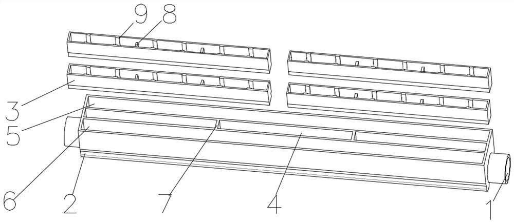
[0096] as attached figure 1 As shown, a laminar flow hollow fiber filter membrane shell, the laminar flow hollow fiber filter membrane shell includes a water production port 1, a water collection pipe 2 and a membrane silk packaging groove 3, and the membrane silk packaging groove 3 Located inside the water collection pipe 2, the water production port 1 is located on the water collection pipe 2, and the air guide port 4 is arranged in the middle of the water collection pipe 2.
[0097] Wherein, the water collecting pipe 2 is divided into a left pipe 5 and a right pipe 6 by the air diversion opening 4 in the middle, and the left pipe 5 and the right pipe 6 are connected by reinforcing ribs. The reinforcing rib 7 between the left pipe 5 and the right pipe 6 can ensure the overall strength of the membrane shell, so that the membrane shell will not be deformed when it is operated in a complex sewage environment for a long time.
[0098]The water production port 1 is located at bo...
Embodiment 2
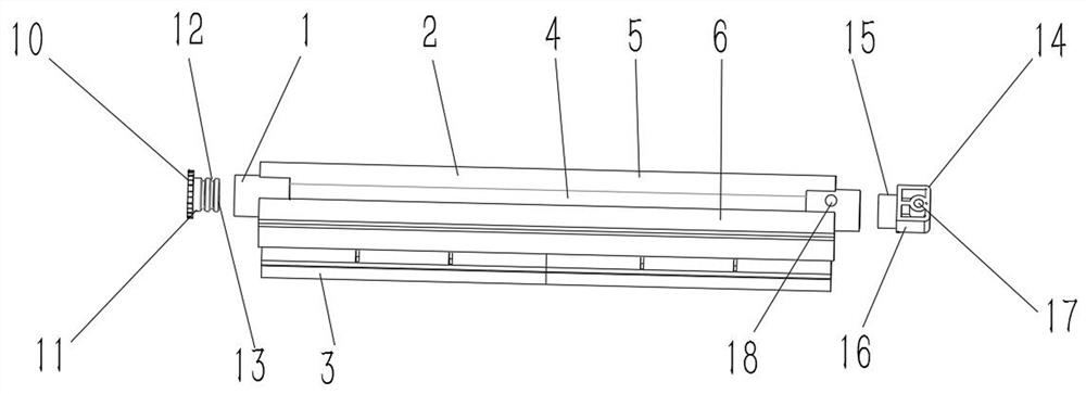
[0101] as attached figure 2 As shown, a laminar flow hollow fiber filter membrane shell, the laminar flow hollow fiber filter membrane shell includes a water production port 1, a water collection pipe 2 and a membrane silk packaging groove 3, and the membrane silk packaging groove 3 Located inside the water collection pipe 2, the water production port 1 is located on the water collection pipe 2, and the air guide port 4 is arranged in the middle of the water collection pipe 2.
[0102] Wherein, the water collecting pipe 2 is divided into a left pipe 5 and a right pipe 6 by the air diversion opening 4 in the middle, and the left pipe 5 and the right pipe 6 are connected by reinforcing ribs. The reinforcing rib 7 between the left pipe 5 and the right pipe 6 can ensure the overall strength of the membrane shell, so that the membrane shell will not be deformed when it is operated in a complex sewage environment for a long time.
[0103] The water production port 1 is located at ...
Embodiment 3
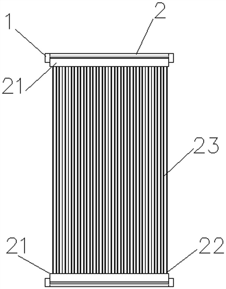
[0110] as attached figure 1 , image 3 , Figure 4 , Figure 5 and Figure 6 As shown, a laminar flow hollow fiber filter membrane, the laminar flow hollow fiber filter membrane includes a membrane case 21, a packaging glue 22 and a membrane wire 23, and the membrane case 21 includes a membrane wire packaging groove 3, a collection The water pipe 2 and the water production port 1, the membrane thread 23 are packaged in the film thread packaging groove 3 through the packaging glue 22, the membrane thread packaging groove 3 is bonded together with the water collection pipe 2 through the membrane shell bonding glue, the water collection pipe 2 and the water production port 1 In the middle of the water collecting pipe 2, an air diversion port 4 is arranged.
[0111] The membrane case 21 includes two rows of membrane filament packaging grooves 3 arranged in parallel, and the air guide port 5 is located in the middle of the two rows of membrane filament packaging grooves 3, and ...
PUM
| Property | Measurement | Unit |
|---|---|---|
| bursting strength | aaaaa | aaaaa |
| bursting strength | aaaaa | aaaaa |
| width | aaaaa | aaaaa |
Abstract
Description
Claims
Application Information
 - R&D
- Intellectual Property
- Life Sciences
- Materials
- Tech Scout
- Unparalleled Data Quality
- Higher Quality Content
- 60% Fewer Hallucinations
Browse by: Latest US Patents, China's latest patents, Technical Efficacy Thesaurus, Application Domain, Technology Topic, Popular Technical Reports.
© 2025 PatSnap. All rights reserved.Legal|Privacy policy|Modern Slavery Act Transparency Statement|Sitemap|About US| Contact US: help@patsnap.com


