

Device and method for bonding 3D grating film and glass
A bonding device and grating film technology, applied in lamination devices, chemical instruments and methods, control lamination, etc., can solve the problems of low bonding efficiency and poor precision of 3D grating film
- Summary
- Abstract
- Description
- Claims
- Application Information
AI Technical Summary
Problems solved by technology
Method used
Image

Examples
Embodiment 1
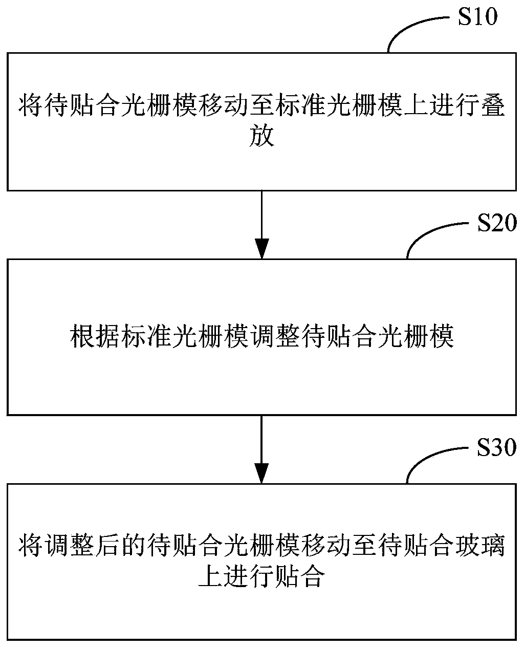
[0024] Embodiment 1 of the present application provides a bonding method of 3D grating film and glass, such as figure 1 As shown, bonding methods include:
[0025] Step S10. Move the grating film to be bonded to the standard grating film for stacking.
[0026] In step S10, the standard grating film is placed at a preset position, and the grating film to be bonded is moved to the preset position. The standard grating film on the position is superimposed, and this step is used to realize the comparison between the grating film to be bonded and the standard grating film.
[0027] Step S20. Adjust the grating film to be bonded according to the standard grating film.
[0028] In step S20, the grating film to be bonded is adjusted according to the standard grating film, so that the position of the grating film to be bonded is the same as that of the standard grating film. For example, there are many lenticular lenses on the grating film to be bonded and the standard grating film. ...
Embodiment 2
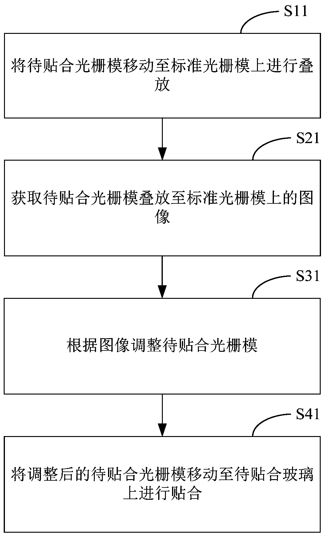
[0033] Embodiment 2 of the present application provides a bonding method of 3D grating film and glass, such as figure 2 As shown, bonding methods include:
[0034] Step S11. Move the grating film to be bonded to the standard grating film for stacking.
[0035] This step is the same as step S10 and will not be repeated here.
[0036] Step S21. Obtain an image of the laminated lenticular film on the standard lenticular film.
[0037] In step S21, after the grating film to be bonded is stacked on the standard grating film, a camera is used to take pictures of the grating film to be bonded and the standard grating film stacked together, so as to obtain the Image on standard lenticular film.
[0038] Step S31. Adjusting the grating film to be bonded according to the image.
[0039] In step S31, after the image is acquired, the image is analyzed to determine whether the image has moiré; when the image has moiré, translate and / or rotate the grating film to be bonded until the mo...
Embodiment 3
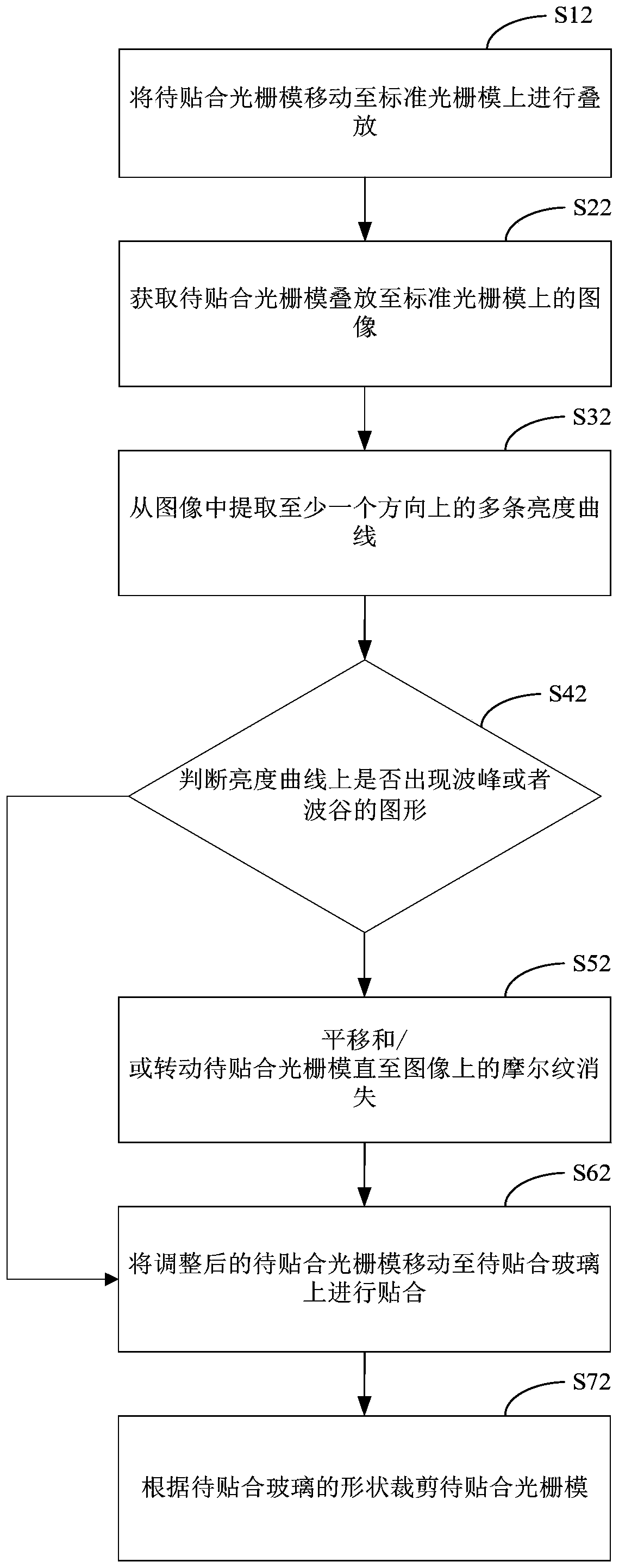
[0044] Embodiment 3 of the present application provides a method for laminating 3D grating film and glass, such as image 3 As shown, bonding methods include:
[0045] Step S12. Move the grating film to be bonded to the standard grating film for stacking.
[0046] This step is the same as step S10 and will not be repeated here.
[0047] Step S22. Acquiring an image of the laminated lenticular film on the standard lenticular film.
[0048] In step S22, after the grating film to be bonded is stacked on the standard grating film, a camera is used to take pictures of the laminated grating film to be bonded and the standard grating film to obtain the Image on standard lenticular film.
[0049] Step S32. Extracting multiple brightness curves in at least one direction from the image.
[0050] Step S42. Judging whether there are peaks or valleys on the luminance curve, if yes, execute step S52; otherwise, execute step S62.
[0051] Step S52. When the image has moiré, translate an...
PUM
 Abstract
Description
Claims
Application Information