A device fault diagnosis method, device, storage medium and electronic device
A technology of equipment and fault status, which is applied in the directions of measuring devices, measuring electricity, measuring electrical variables, etc., can solve the problems of high cost of overhauling equipment, inability to quickly locate equipment faults on site, etc., and achieve the effect of troubleshooting
- Summary
- Abstract
- Description
- Claims
- Application Information
AI Technical Summary
Problems solved by technology
Method used
Image
Examples
Embodiment 2
[0033] In order to solve the problems existing in the prior art, the present invention provides a fault diagnosis method for equipment. In order to make the purpose, technical solution and effect of the present invention clearer and clearer, the present invention will be further described in detail below with reference to the accompanying drawings and examples. It should be understood that the specific embodiments described here are only used to explain the present invention, not to limit the present invention.
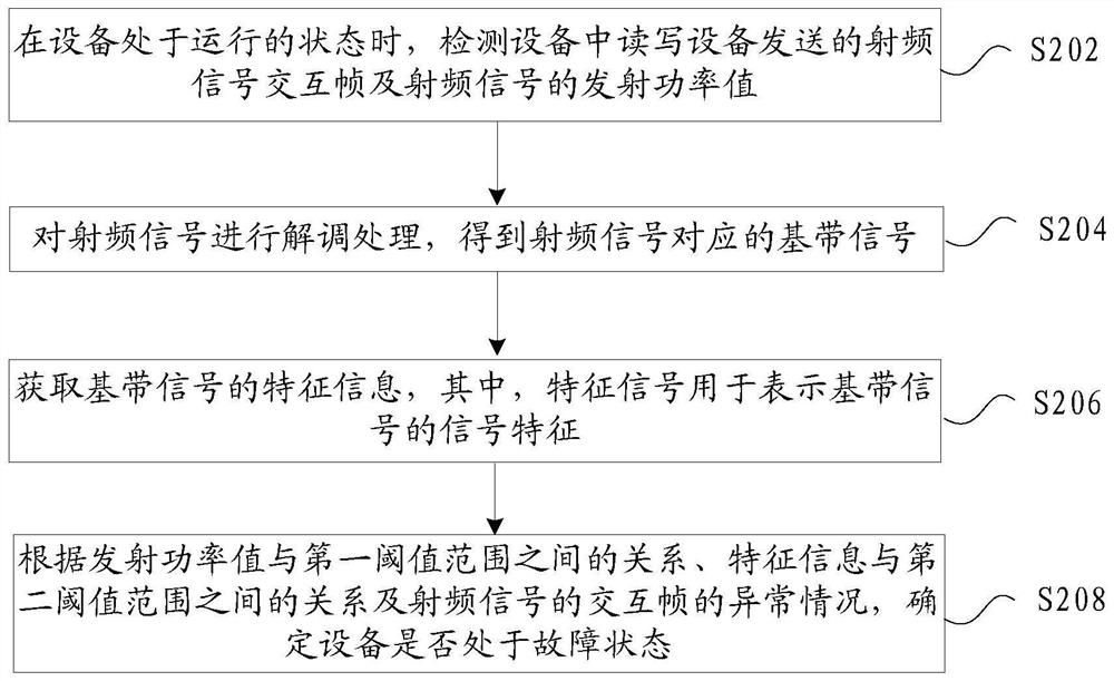
[0034] figure 2It is a flow chart of a fault diagnosis method for equipment according to an embodiment of the present invention, such as figure 2 As shown, the process includes the following steps:
[0035] Step S202, when the device is in the running state, detect the radio frequency signal interaction frame sent by the read-write device in the device and the transmit power value of the radio frequency signal;
[0036] Step S204, demodulating the radio frequency ...
Embodiment 3
[0068] In this embodiment, a device fault diagnosis device is also provided, and the device is used to implement the above embodiments and preferred implementation modes, and what has already been described will not be repeated. As used below, the term "module" may be a combination of software and / or hardware that realizes a predetermined function. Although the devices described in the following embodiments are preferably implemented in software, implementations in hardware, or a combination of software and hardware are also possible and contemplated.
[0069] Figure 7 is a structural block diagram of a device diagnostic device according to an embodiment of the present invention, such as Figure 7 As shown, the device includes a detection module 702, which is used to detect the radio frequency signal interaction frame and the transmission power value of the radio frequency signal sent by the read-write device in the device when the device is in a running state; the demodulat...
Embodiment 4
[0080] An embodiment of the present invention also provides a storage medium, in which a computer program is stored, wherein the computer program is set to execute the steps in any one of the above method embodiments when running.
[0081] Optionally, in this embodiment, the above-mentioned storage medium may include but not limited to: U disk, read-only memory (Read-Only Memory, ROM for short), random access memory (Random Access Memory, RAM for short), Various media that can store computer programs, such as removable hard disks, magnetic disks, or optical disks.
[0082] An embodiment of the present invention also provides an electronic device, including a memory and a processor, where a computer program is stored in the memory, and the processor is configured to run the computer program to perform the steps in any one of the above method embodiments.
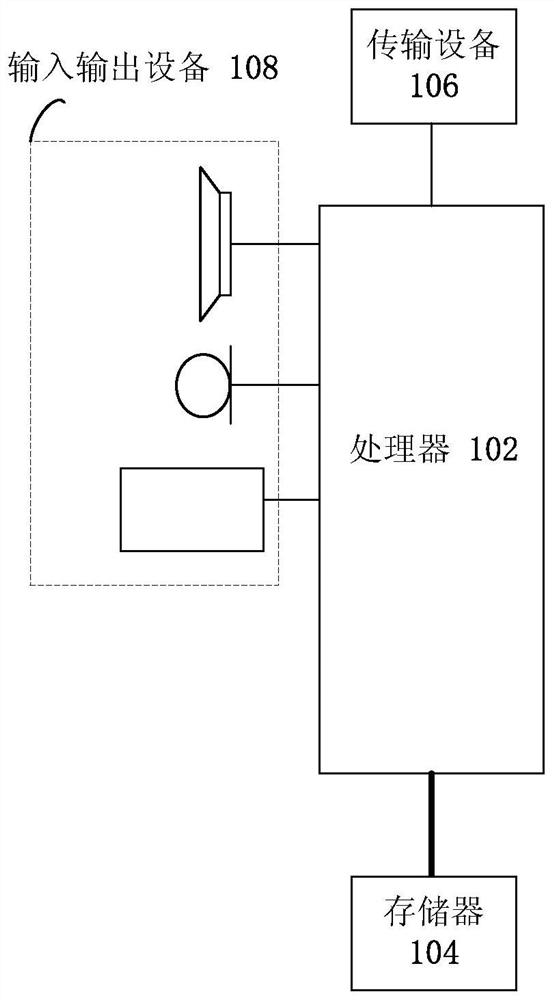
[0083] Optionally, the above-mentioned electronic device may further include a transmission device and an input-output devi...
PUM
 Abstract
Description
Claims
Application Information
 - R&D
- Intellectual Property
- Life Sciences
- Materials
- Tech Scout
- Unparalleled Data Quality
- Higher Quality Content
- 60% Fewer Hallucinations
Browse by: Latest US Patents, China's latest patents, Technical Efficacy Thesaurus, Application Domain, Technology Topic, Popular Technical Reports.
© 2025 PatSnap. All rights reserved.Legal|Privacy policy|Modern Slavery Act Transparency Statement|Sitemap|About US| Contact US: help@patsnap.com


