Deforming energy-absorbing anchor ring and anchor rod supporting method for preventing anchor rod from being broken and catapulted

A bolt support and bulletproof technology, which is applied in the installation of bolts, the measurement of the change force of the optical properties of the material when it is stressed, and the earth cube drilling and mining, etc., can solve the problems of long operation time, slowing down the excavation speed, Problems such as blindness and unpredictability can achieve the effect of preventing accidents, improving safety, and delaying premature failure

Inactive Publication Date: 2019-05-14
CHINA UNIV OF MINING & TECH
View PDF13 Cites 4 Cited by
  • Summary
  • Abstract
  • Description
  • Claims
  • Application Information

AI Technical Summary

Problems solved by technology

Some coal mines use the method of "capping" or "wrapping iron wire" on the tail of the bolt to prevent potential fracture ejection, which is blind and unpredictable
If all bolting systems are adopted in this way, some bolting systems will not actually eject in the end during the normal service of the roadway, which will cause long operation time and slow down the excavation speed.

Method used


Image

  • Deforming energy-absorbing anchor ring and anchor rod supporting method for preventing anchor rod from being broken and catapulted
  • Deforming energy-absorbing anchor ring and anchor rod supporting method for preventing anchor rod from being broken and catapulted
  • Deforming energy-absorbing anchor ring and anchor rod supporting method for preventing anchor rod from being broken and catapulted

Examples


Embodiment Construction

[0032] The present invention will be further described below in conjunction with the embodiment in the accompanying drawings:

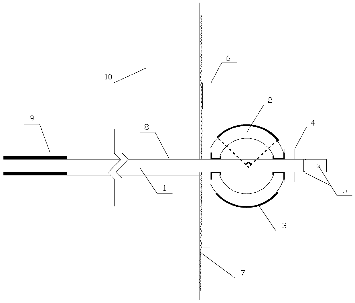
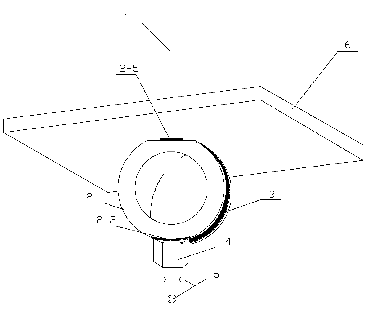
[0033] Such as figure 1As shown, the deformed energy-absorbing anchor ring of the present invention and the bolt support device for preventing the bolt from breaking and ejecting include the anchor rod 1 extending into the borehole 8 and fixed by the anchoring agent 9, and the anchor rods exposed in the hole are arranged in sequence. 1. On the barbed wire 7, the tray 6 and the nut 4, there are two openings 5 ​​at the end of the anchor bar that are intersected in a cross shape at the tail of the anchor bar 1, and an anchor ring 2 is provided between the tray 6 and the nut 4 , the anchor ring 2 is provided with a facing hole that is sheathed on the anchor rod 1, and the contact ends of the anchor ring 2, the tray 6 and the nut 4 are planes, which are respectively the bonding surface of the nut end of the anchor ring and the tray end of the anchor ring ...


PUM

PropertyMeasurementUnit
yield strengthaaaaaaaaaa

Abstract

The invention discloses a deforming energy-absorbing anchor ring and an anchor rod supporting method for preventing an anchor rod from being broken and catapulted, and is particularly suitable for soft rock large-deformation roadways or sections needing energy-absorbing yielding supporting. The anchor rod penetrates through the anchor ring with opposite holes, pressure is applied to rock mass through a tray and a nut, and deformation is prevented. When the stress of the anchor rod is increased, the anchor ring deforms in the direction opposite to the holes, and thus the energy-absorbing effectis achieved. The deformation amplitude of the anchor ring can be observed by utilizing fluorescent bands oppositely arranged on the outer side of the anchor ring, so that the stress of the anchor rodis pre-judged, and a warning effect on sudden breakage of a potential part is achieved. When the deformation of the anchor ring is too large or the fluorescence range is too large, anti-ejection ironwires penetrate through two penetrating holes which are formed in the tail portion of the anchor rod in a crossed mode and screwed and fixed on an iron wire net. If the anchor rod is broken at any key position, the two anti-ejection iron wires which are arranged in the crossed mode can prevent the anchor rod from being catapulted into the space of the roadway, and people are prevented from beinginjured. The deforming energy-absorbing anchor ring is simple in structure, convenient to operate, low in economic cost, safe, reliable and good in effect.

Description

technical field [0001] The invention relates to a bolt support method, in particular to a deformed energy-absorbing anchor ring suitable for soft rock large-deformation roadways or sections requiring pressure-absorbing and pressure-absorbing support to protect the safety of miners and to prevent bolt breakage and ejection. Anchor support method. Background technique [0002] Bolt support technology plays an extremely important role in the field of coal mine support in my country, and has obvious economic and technical benefits, so it is widely popularized and applied. In recent years, with the increase of coal mining depth, many mines can encounter large deformation roadways in soft rock or roadways with impact tendencies such as rockbursts. Such roadways have high original rock stress and complex stress disturbances, and most roadways have to withstand a Or multiple mining disturbances. At present, most projects tend to use intensive support, extended support, super suppo...

Claims


Application Information

Patent Timeline
Patent Type & Authority Applications(China)
IPC IPC(8): E21D21/00E21D20/00G01L1/24G01B11/16
CPCE21D20/00E21D21/00G01B11/16G01L1/24
Inventor 冯晓巍汪明坤张农何青源
Owner CHINA UNIV OF MINING & TECH
Why Eureka
Try Eureka