Air cooling device for battery of new energy automobile

A new energy vehicle, air cooling device technology, applied in the direction of secondary batteries, circuits, electrical components, etc., can solve the problem that the heat of the power battery pack cannot be dissipated in time.

Inactive Publication Date: 2019-05-14
孙钰涵
View PDF6 Cites 5 Cited by
  • Summary
  • Abstract
  • Description
  • Claims
  • Application Information

AI Technical Summary

Problems solved by technology

[0003] The purpose of the present invention is to provide a new energy vehicle battery air cooling device, aiming to improve the problem that the heat generated by the power battery pack cannot be dissipated in time when the new energy vehicle is running with the power battery pack as the power supply

Method used


Image

  • Air cooling device for battery of new energy automobile
  • Air cooling device for battery of new energy automobile
  • Air cooling device for battery of new energy automobile

Examples


Embodiment 1

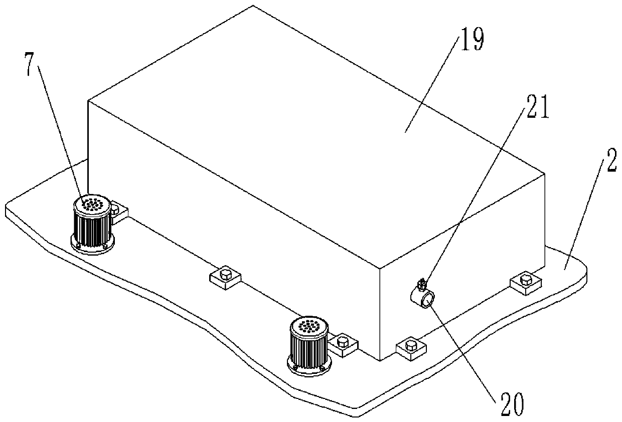
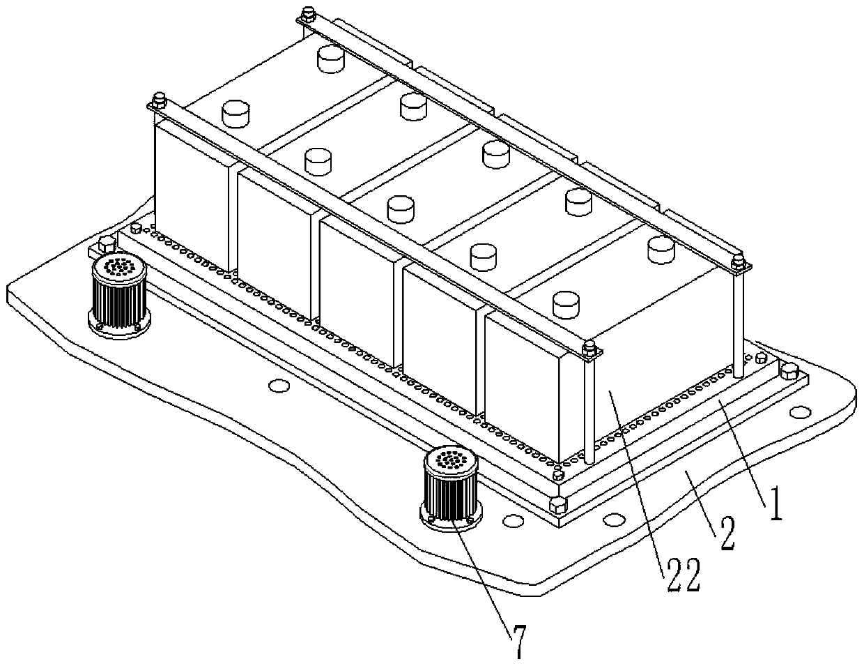
[0039] Example 1: Please refer to figure 2 , Figure 4 , Figure 7 and Figure 8 , a new energy vehicle battery air cooling device, including a base 1 for installing a battery 22 and a mounting plate 2 for installing the base 1, the mounting plate 2 is installed on the frame of the car, and the base 1 consists of a flat box 101 with an open lower end It is composed of a bottom plate 102 connected to the lower end of the box body 101. Several grooves 103 for installing the battery 22 are arranged on the upper end surface of the box body 101. The shape and size of the cross section of the groove 103 are the same as the shape and size of the bottom cross section of the battery. The upper end surface of the box body 101 is located on the outer side of the groove 103, and there are vent holes 104 all over the place, and the lower end surface of the bottom plate 102 is provided with an air intake through hole 105 leading to the box body 101, and the air intake through hole 105 is...

Embodiment 2

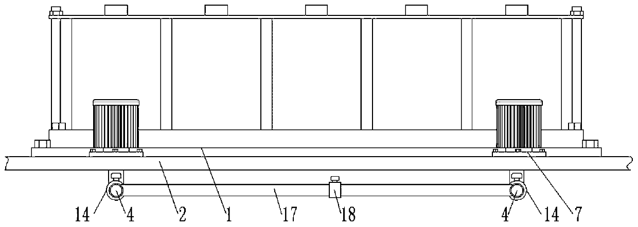
[0048] Embodiment two: the air intake through hole 105, the gas collection cover 3, the first air pipe 4, the second air pipe 5, the rotary joint 6, the rotary drive device and the baffle plate 13 are all provided with two groups, and the first air pipe 4 or the first air pipe of each group or The second air pipe 5 is provided with a first valve 14, the gas collecting cover 3 is bell-shaped, and the large diameter end faces the front of the car, and the two first valves 14 can be opened to make the two gas collecting covers 3 cool the battery. 22 of the wind collection, only one first valve 14 can be opened, and only one gas collecting hood 3 is used to collect the wind for cooling the battery 22, which further strengthens the adjustment effect on the cooling air volume.

[0049] Such as Figure 13 and Figure 14 As shown, the inner wall of the gas collecting hood 3 is fixedly provided with a plurality of mounting pieces 15, the mounting pieces 5 are provided with threaded ho...


PUM


Abstract

The invention discloses an air cooling device for a battery of a new energy automobile. The air cooling device comprises a base for installing the battery, wherein the base consists of a flat box bodywith an opening at the lower end and a bottom plate that is connected to the lower end of the box body, the upper end surface of the box body is provided with a plurality of grooves for installing the battery, ventilation holes are distributed on the upper end surface of the box body and located outside the grooves, the lower end surface of the bottom plate is provided with an air inlet through hole leading to the box body, an air inlet pipeline is connected to the air inlet through hole, an air collecting cover is arranged at the front end of the air inlet pipeline, and the big mouth end ofthe air collecting cover faces the front of the automobile; when the new energy automobile is running, the outside air enters the box body through the air collecting cover and the air inlet pipeline,and then is discharged through the ventilation holes, and since the ventilation holes are distributed around each battery, the heat emitted by each battery can be uniformly blown away; and according to the scheme of the invention, the heat generated by a power battery can be dissipated in time, and the problem that the performance and the service life of the battery are influenced because the heatgenerated by the power battery cannot be dissipated in time cannot occur.

Description

technical field [0001] The invention relates to the field of new energy vehicle battery cooling devices, in particular to a new energy vehicle battery air cooling device. Background technique [0002] New energy vehicles refer to all other energy vehicles except gasoline and diesel engines, including fuel cell vehicles, hybrid vehicles, hydrogen energy vehicles and solar vehicles. In the process of new energy vehicles running with the power battery pack as the power source, the discharge of the power battery pack generates a lot of heat. If the heat cannot be dissipated in time, it will seriously affect the performance of the battery and the service life of the battery. Contents of the invention [0003] The purpose of the present invention is to provide a new energy vehicle battery air cooling device, aiming to improve the problem that the heat generated by the power battery pack cannot be dissipated in time when the new energy vehicle is running with the power battery pa...

Claims


Application Information

Patent Timeline
Patent Type & Authority Applications(China)
IPC IPC(8): H01M10/613H01M10/625H01M10/635H01M10/6556H01M10/6563
CPCY02E60/10
Inventor 孙钰涵徐沁墨
Owner 孙钰涵
Why Eureka
Try Eureka