
Self-lubricating mechanical commutator

A mechanical commutation and commutator technology, applied in the direction of current collectors, rotary current collectors, electrical components, etc., can solve the problems of difficulty in reducing the internal friction force of the commutator, reducing the service life of the commutator, time-consuming and laborious, etc. , to save manpower and time, prolong service life and reduce friction

Pending Publication Date: 2019-05-14
JIANGSU LIFENG ELECTROMECHANICAL
View PDF0 Cites 0 Cited by
  • Summary
  • Abstract
  • Description
  • Claims
  • Application Information

AI Technical Summary

Problems solved by technology

The commutators used in automotive starters are mainly mechanical arched commutators and plastic commutators; and the commutator will be coated with lubricant on its surface before use to reduce the commutator's contact with other parts during operation. However, the existing mechanical commutator can only apply lubricant on its surface to reduce the friction between the surface of the commutator and other parts, but it is difficult to reduce the friction inside the commutator. To a certain extent, the service life of the commutator is reduced. When the interior of the commutator needs to be lubricated, it is necessary to manually apply lubricant to the surface of the commutator, so that the lubricant penetrates into the interior of the commutator, which is time-consuming and laborious. Therefore, we propose a self-lubricating mechanical commutator to solve the above problems

Method used


Image

  • Self-lubricating mechanical commutator
  • Self-lubricating mechanical commutator
  • Self-lubricating mechanical commutator

Examples


Embodiment Construction

[0016] The following will clearly and completely describe the technical solutions in the embodiments of the present invention with reference to the accompanying drawings in the embodiments of the present invention. Obviously, the described embodiments are only some of the embodiments of the present invention, not all of them. Based on the embodiments of the present invention, all other embodiments obtained by persons of ordinary skill in the art without making creative efforts belong to the protection scope of the present invention.

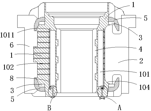
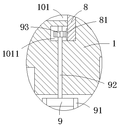
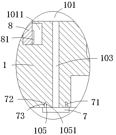
[0017] see Figure 1-4 , the present invention provides a technical solution: a self-lubricating mechanical commutator, including a commutator body 1, a commutator segment 2, a gasket 3, a reinforcement ring 5, a mica sheet 6 and a bushing 4, and the commutator body 1 The outer wall of the outer wall is equidistantly provided with a card slot 104 matched with the commutator segment 2, the commutator segment 2 is clamped in the card slot, the mica...


PUM


Abstract

The invention discloses a self-lubricating mechanical commutator. The self-lubricating mechanical commutator comprises a commutator body, reversing pieces, a gasket, a reinforcing ring, mica sheets and a bush; clamping grooves matched with the reversing pieces are formed in the outer side wall of the commutator body at equal intervals; the reversing pieces are clamped in the clamping grooves, andthe mica sheets are arranged between the two reversing pieces; the commutator body is sequentially sleeved with the reinforcing ring and the gasket from the upper end and the lower end to the middle;one end, far away from the commutator body, of the reinforcing ring is clamped at the end parts of the reversing pieces and the mica sheets; the bush is fixedly connected to the inner side wall of thecommutator body; an annular cavity for containing a lubricant is formed in the side wall of the commutator body; according to the commutator, the commutator can be lubricated automatically, so that manpower and time are saved; and the lubricant seeps out of the outside through the interior of the commutator, so that the friction in the commutator can be reduced, and the service life of the commutator is prolonged to a certain extent.

Description

technical field [0001] The invention relates to a commutator, in particular to a self-lubricating mechanical commutator. Background technique [0002] The commutator is a component used for current commutation on DC motors and AC series motors, in order to allow the motor to continue to rotate, commonly known as a commutator; structurally, the commutator is a circle of several contact pieces, connected separately For each contact on the rotor, the two electrodes connected outside are called brushes, and only two of them are in contact at the same time. The commutator includes: mechanical commutator, semi-plastic commutator, all-plastic commutator device. The commutators used in automotive starters are mainly mechanical arched commutators and plastic commutators; and the commutator will be coated with lubricant on its surface before use to reduce the commutator's contact with other parts during operation. However, the existing mechanical commutator can only apply lubricant ...

Claims


Application Information

Patent Timeline
Patent Type & Authority Applications(China)
IPC IPC(8): H01R39/04
Inventor 白洪楷白直金黄华
Owner JIANGSU LIFENG ELECTROMECHANICAL
Learn More