Detachable structure for shoes and clothing and intelligent coat with detachable power supply

A technology of power supply and jacket, applied in the field of clothing, can solve the problems of taking out or replacing the power supply, reducing the service life of the power supply, inconvenient battery recycling, etc., achieving the effect of simple taking out or replacing the power supply, improving the service life, and convenient loading and unloading of the power supply

Pending Publication Date: 2019-05-17
黑天鹅智能科技(福建)有限公司
View PDF1 Cites 0 Cited by
  • Summary
  • Abstract
  • Description
  • Claims
  • Application Information

AI Technical Summary

Problems solved by technology

[0002] Today's smart shoes and clothing generally install smart devices in the shoes or in the interlayer of clothes, and the power supply for the smart devices is also packaged in the shoes or in the interlayer of clothes. However, this is not environmentally friendly and is not convenient for batteries. Recycling, and shoes or clothes need to be cleaned from time to time. If the power supply is not taken out when the shoes or clothes are cleaned, it is easy to soak the power supply and reduce the service life of the power supply. However, taking out or replacing the power supply is cumbersome, cumbersome, time-consuming and laborious

Method used


Image

  • Detachable structure for shoes and clothing and intelligent coat with detachable power supply
  • Detachable structure for shoes and clothing and intelligent coat with detachable power supply
  • Detachable structure for shoes and clothing and intelligent coat with detachable power supply

Examples


Embodiment 1

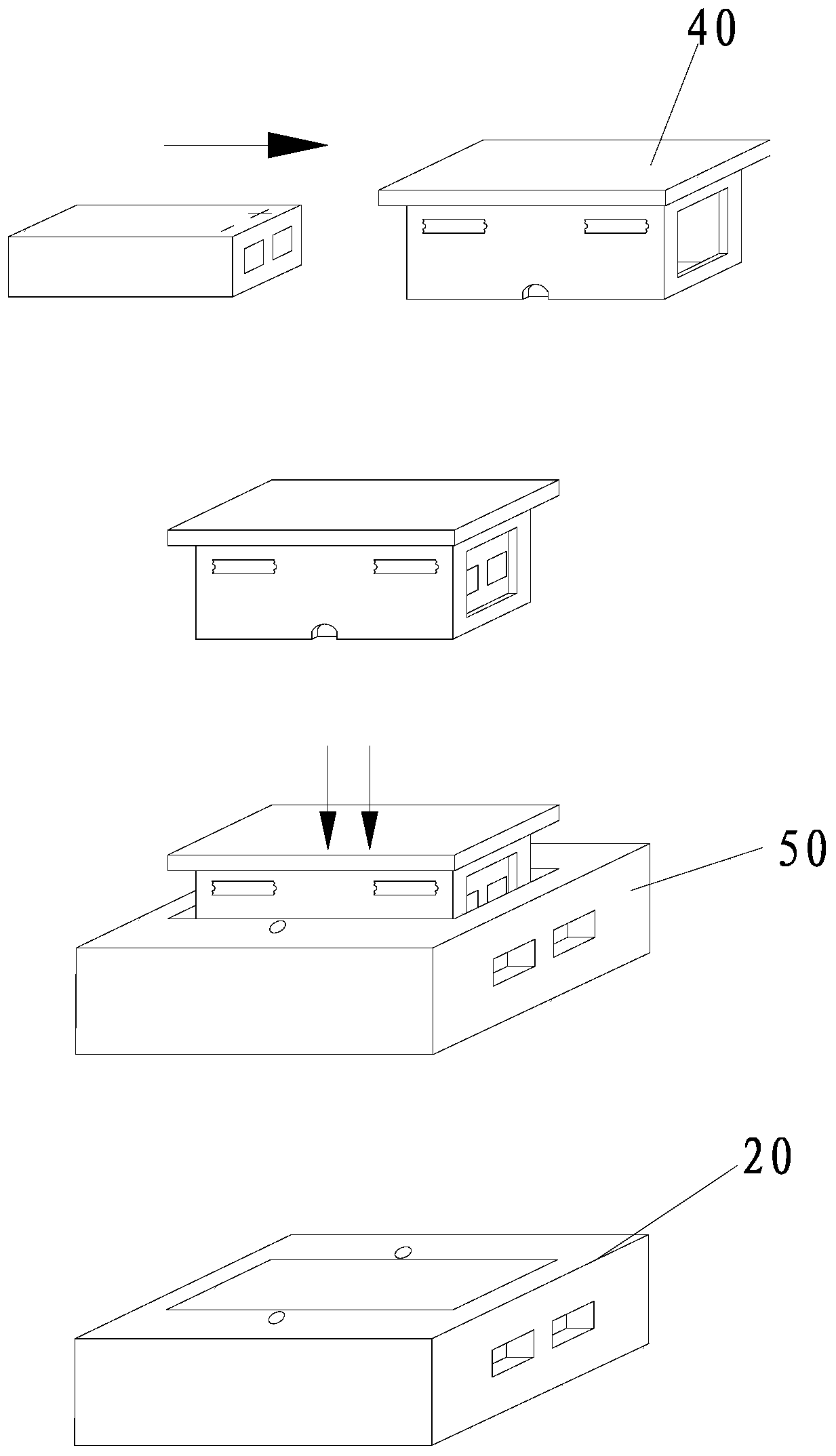
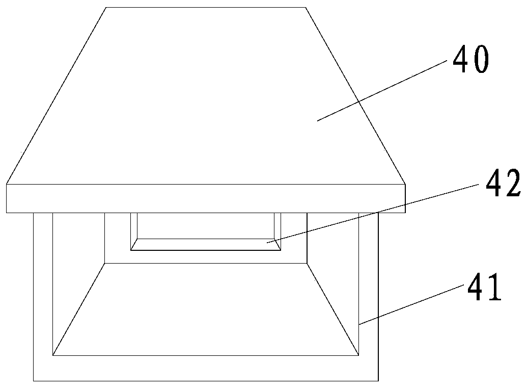
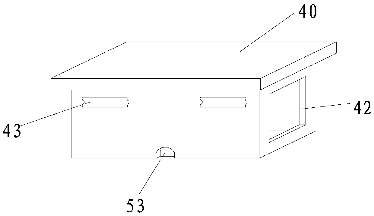
[0073] Such as Figure 1-5 As shown, the inlet and outlet 21 are located on the upper side of the outer box body 50 in this embodiment, so that the inner box body 40 enters and exits the outer box body 50 along the up-down direction.

[0074] Specifically, the inner box body 40 is provided with an inner box opening 41 and an electrode hole 42, and the electrode hole 42 is used for extending the electrode end of the power supply, and the inner box opening 41 and the electrode hole 42 are all connected with the inner chamber of the inner box body 40. connected, and the inner box opening 41 and the electrode hole 42 are arranged oppositely, and a conductive hole 51 is opened on the side wall of the outer box body 50, and the conductive hole 51 is located at the rear side of the outer box body 50, and the inner box body 40 and the outer box body After 50 is installed, the conductive hole 51 is opposite to the electrode hole 42, and a conductive sheet is inserted in the conductive ...

Embodiment 2

[0081] Such as Figure 6-9 As shown, the inlet and outlet 21 are located on the upper side of the outer box body 50 in this embodiment.

[0082] The inner box body 40 is provided with an inner box opening 41 and an electrode hole 42. The electrode end of the electrode hole 42 is used for the power supply to extend outside the inner box body 40. The inner box opening 41 and the electrode hole 42 are all connected to the inner box body 40. The inner cavity is connected, and the inner box opening 41 and the electrode hole 42 are respectively located on two adjacent side walls of the inner box body 40, and a conductive hole 51 is opened on the side wall of the outer box body 50, and the conductive hole 51 is connected with the ejection hole. 22 opposite to each other, that is, the conductive hole 51 is arranged on the lower side wall of the outer box body 50. After the inner box body 40 and the outer box body 50 are installed, the conductive hole 51 is opposite to the electrode ho...

Embodiment 3

[0091] Such as Figure 10-11 As shown, in this embodiment, the sole equipped with power supply, smart device and loading and unloading assembly is called smart shoe sole, that is, a smart shoe sole with a detachable power supply. The smart shoe sole includes a power supply, a smart device and a loading and unloading structure. The device provides working power, that is, the power input terminal of the smart device is electrically connected to the output terminal of the power supply, and the loading and unloading structure includes the loading and unloading assembly described in the first embodiment.

[0092] The smart sole also includes a sole body 60. The sole body 60 includes an outsole 61 and a midsole 62 arranged on the outsole 61. The outsole 61 is provided with an installation groove group 611, and the smart device is installed in the installation groove group 611.

[0093] It should be noted that the aforementioned smart device is a known smart device. For example, the ...


PUM


Abstract

The invention discloses a detachable structure for shoes and clothing. The detachable structure comprises a mounting and removal assembly, wherein the mounting and removal assembly is mounted on a shoe or clothing with an intelligent device; the power input end of the intelligent device is electrically connected with the output end of a power supply; the mounting and removal assembly comprises a receiving box and a rotating piece mounted in the receiving box in a rotatable manner; an ejection hole and an inlet/outlet for letting the power supply to get in and get out are formed in the receiving box; the first end of the rotating piece corresponds to the inlet/outlet; the ejection hole corresponds to the second end of the rotating piece; two ends of the rotating piece are located in the same plane. Compared with the prior art, the detachable structure has the advantages that the rotating piece is mounted in an inner cavity of the receiving box, and the power supply is placed in the receiving box; during removal of the power supply, the second end of the rotating piece moves towards the bottom of the inner cavity of the receiving box to drive the first end of the rotating piece to move towards the inlet/outlet to eject the power supply. The detachable structure disclosed by the invention is simple, and the power supply is convenient to mount and remove; furthermore, the power supply is taken out or replaced more easily and quickly. The invention further provides an intelligent coat with a detachable power supply.

Description

technical field [0001] The invention relates to the field of clothing, and more specifically relates to a smart jacket with a detachable structure for shoes and clothing and a detachable power supply. Background technique [0002] Today's smart shoes and clothing generally install smart devices in the shoes or in the interlayer of clothes, and the power supply for the smart devices is also packaged in the shoes or in the interlayer of clothes. However, this is not environmentally friendly and is not convenient for batteries. Recycling, and shoes or clothes need to be cleaned from time to time. If the power supply is not taken out when the shoes or clothes are cleaned, it is easy to soak the power supply and reduce the service life of the power supply. However, taking out or replacing the power supply is cumbersome, cumbersome, time-consuming and laborious . Contents of the invention [0003] The object of the present invention is to provide a detachable structure for shoe...

Claims


Application Information

Patent Timeline
Patent Type & Authority Applications(China)
IPC IPC(8): A41D1/00A41D27/00A43B3/00
Inventor 蔡清来吴英丽廖洪波王陈杨斯理
Owner 黑天鹅智能科技(福建)有限公司
Why Eureka
Try Eureka