
3D printing building spray head and imprinting method

A 3D printing and printing head technology, applied in the field of 3D printing, can solve the problems of reducing construction efficiency and embossing operation difficulties

Active Publication Date: 2019-05-17
GUANGZHOU UNIVERSITY
View PDF14 Cites 0 Cited by
  • Summary
  • Abstract
  • Description
  • Claims
  • Application Information

AI Technical Summary

Problems solved by technology

[0003] For general 3D printing technology, the printed structures are generally relatively small. Using a small print head can not only meet the printing speed requirements, but also meet the precision requirements of the structure, and can also print some vivid patterns. For the construction industry 3D printers, the buildings to be printed are much larger than ordinary small structures, and the nozzles of the corresponding printers are also much larger. In the actual printing process, for some detailed patterns, such as patterns and other effects, large-scale The nozzle cannot meet the printing requirements due to its own size and operating speed limitations, and additional embossing operations are required in the later stage. Since the building materials gradually condense and harden during the layer-by-layer accumulation process, it brings great difficulties to the later imprinting operations. , which greatly reduces the construction efficiency

Method used


Image

  • 3D printing building spray head and imprinting method
  • 3D printing building spray head and imprinting method

Examples


Embodiment Construction

[0022] The specific implementation manners of the present invention will be further described in detail below in conjunction with the accompanying drawings and embodiments. The following examples are used to illustrate the present invention, but are not intended to limit the scope of the present invention.

[0023] In the description of the present invention, it should be understood that the orientation or positional relationship indicated by the terms "upper", "lower", "left", "right", "top", "bottom" etc. Orientation or positional relationship is only for the convenience of describing the present invention and simplifying the description, and does not indicate or imply that the referred device or element must have a specific orientation, be constructed and operated in a specific orientation, and thus should not be construed as a limitation of the present invention.

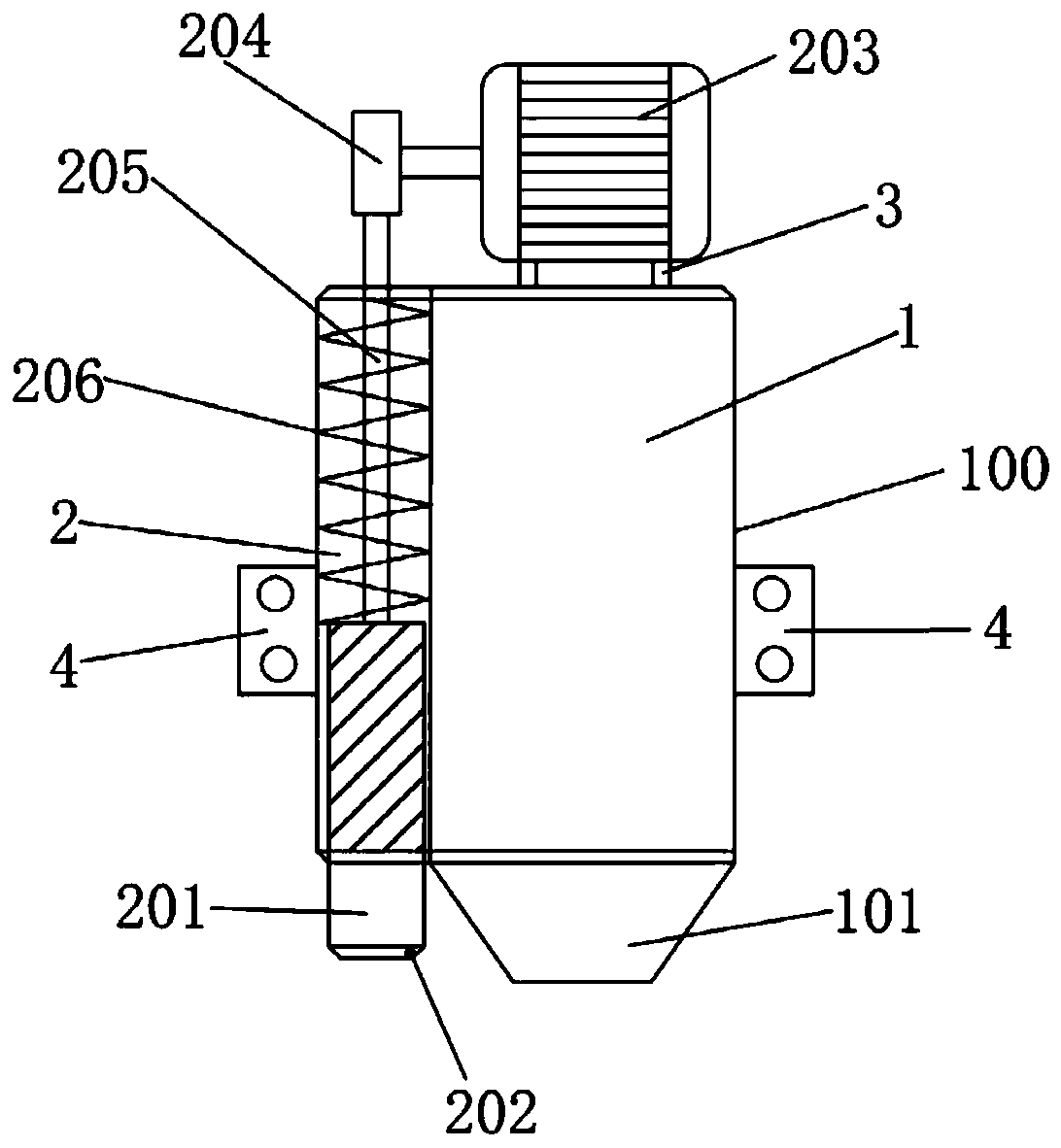
[0024] combine figure 1 As shown, a 3D printing building sprinkler head according to an embodiment of the pr...


PUM


Abstract

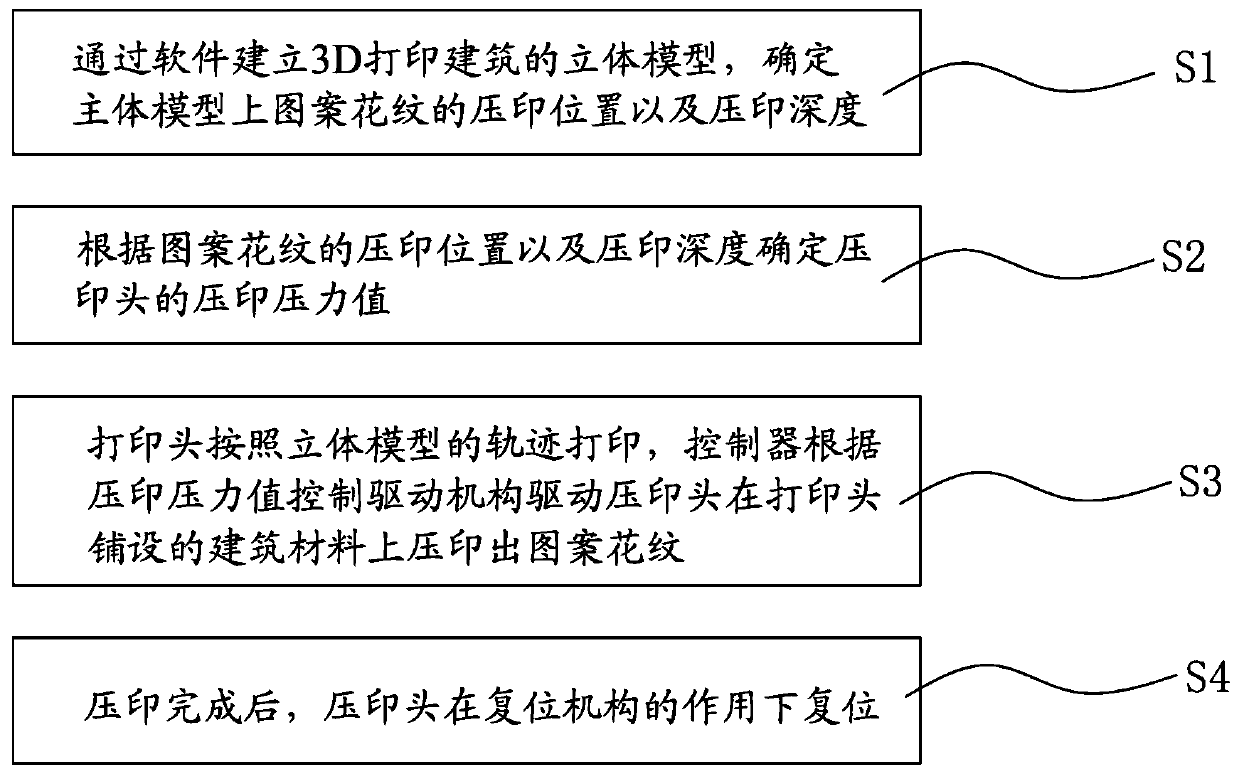
The invention relates to the technical field of 3D printing, and discloses a 3D printing building spray head and an imprinting method. The 3D printing building spray head comprises a shell body, wherein a first cavity and a second cavity are formed in the shell body, a printing head is connected to the lower end of the first cavity, and an imprinting head and a driving mechanism are arranged in the second cavity. According to the 3D printing building spray head and the imprinting method, a product is formed by repeatedly layering building materials layer by layer through the printing head, according to an imprinting pressure value, the driving mechanism is controlled by a controller to drive the imprinting head to imprint patterns on the building materials laid by the printing head, the imprinting head is not limited by the size of the printing rate of the printing head due to the fact that the printing head and the imprinting head are separately arranged, the imprinting head can be individually controlled by the driving mechanism according to specific requirements of the patterns, the imprint effect is good, furthermore, due to the fact that the printing head and the imprinting head are arranged on the same shell body, after the printing head finishes printing, the imprinting head can timely imprint patterns on the building materials laid by the printing head before the building materials are coagulated and hardened, and the imprint construction efficiency is improved.

Description

technical field [0001] The invention relates to the technical field of 3D printing, in particular to a 3D printing building nozzle and an embossing method. Background technique [0002] With the development of 3D printing technology, 3D printing has been applied more and more in the construction industry. 3D printing architecture is an emerging technology that uses industrial robots to repeatedly lay down material layer components in a free-form architectural structure. After layer-by-layer accumulation, a finished product is finally formed. Generally, in order to enhance the aesthetics of the printed product, during the printing process, the printing nozzle Under the action of pressure, the thickness of the material changes, and according to the preset computer program, the undulating pattern or characters are pressed on the surface of the material according to a certain trajectory. [0003] For general 3D printing technology, the printed structures are generally relativel...

Claims


Application Information

Patent Timeline
IPC IPC(8): B29C64/209B29C64/20B29C64/393E04G21/00B33Y30/00B33Y50/02
Inventor 欧阳小伟许世达刘子阳马玉玮
Owner GUANGZHOU UNIVERSITY
Learn More