
Cloth cutting and embossing equipment

A technology for embossing and cloth, which is applied in the field of cloth cutting and embossing equipment, which can solve the problems of uneven embossing, uneven force, and uneven linear force of the embossing device, so as to achieve uniform embossing force and improve Embossing effect, the effect of guaranteeing the embossing effect

Pending Publication Date: 2021-12-21
SICHUAN SHENGSHAN BAIYULAN IND CO LTD
View PDF0 Cites 0 Cited by
  • Summary
  • Abstract
  • Description
  • Claims
  • Application Information

AI Technical Summary

Problems solved by technology

[0002] Before the fabric is made into clothes, it needs to be flattened, cut, embossed, etc. The existing fabric cutting devices mostly use laser cutters or cutting blades to cut the fabric in a straight line, and the fabric needs to be curved or rounded. For arc cutting, the knives of ordinary cutting devices need complex linkage to achieve arc or arc cutting, which is inconvenient to use and cumbersome to operate
At the same time, the traditional cloth embossing device directly embosses the surface of the cloth through the embossing roller with embossing, but the direct embossing of the embossing roller has the problem of uneven linear force, which leads to the final embossing of the cloth surface. Forming has different shades and uneven force
[0003] Therefore, aiming at the problems of the existing cloth cutting device that the combination of cutting lines is not flexible enough and the embossing device is uneven, the present invention discloses a cloth cutting and embossing equipment.

Method used


Image

  • Cloth cutting and embossing equipment
  • Cloth cutting and embossing equipment
  • Cloth cutting and embossing equipment

Examples


Embodiment 1

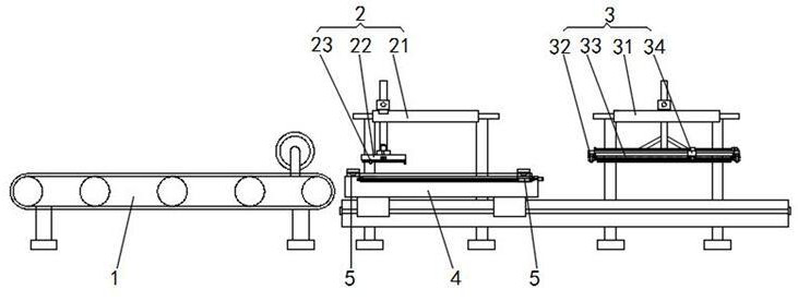
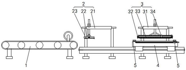
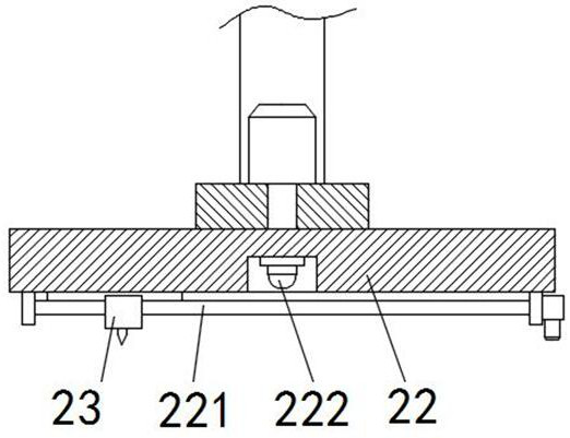
[0026] A kind of cloth cutting and embossing equipment of this embodiment, such as Figure 1-Figure 6 As shown, it includes a feeding device 1, and the discharge end of the feeding device 1 is sequentially provided with a laser cutting device 2 and an embossing device 3 along the cloth conveying direction. A moving stage 4 that moves linearly between the cutting device 2 and the embossing device 3, and cloth tensioning fixtures 5 are arranged on both sides of the moving stage 4 parallel to the direction of cloth transmission; the laser cutting device 2 includes a cutting three-axis moving device 21, a turntable 22 is installed on the moving end of the cutting three-axis moving device 21, and a cutting laser instrument 23 is arranged on the bottom of the turntable 22 for linear movement; the embossing device 3 includes an embossing three-axis moving device 31, an embossing fixture 32 is arranged on the moving end of the embossing three-axis moving device 31, and an embossing te...

Embodiment 2

[0030] This embodiment is further optimized on the basis of embodiment 1, such as Figure 4 As shown, the cloth tensioning fixture 5 includes a tensioning fixture 51, a cloth linear moving device 52, and a measuring grating, and the cloth linear moving device 52 is arranged on the moving stage 4 along the cloth conveying direction and is parallel to the cloth conveying direction. On both sides, one end of the cloth linear moving device 52 close to the feeding device 1 is fixedly provided with a tensioning fixture 51, and the moving end of the cloth linear moving device 52 is also provided with a tensioning fixture 51, and the cloth linear moving device 52 A measuring grating is arranged parallel to one side.

[0031]For ease of description, the fixedly installed tensioning fixture 51 is named as a fixed tensioning fixture 51 , and the tensioning fixture 51 installed on the moving end of the cloth linear moving device 52 is named as a moving tensioning fixture 51 . One end whe...

Embodiment 3

[0034] This embodiment is further optimized on the basis of above-mentioned embodiment 1 or 2, such as Figure 4 As shown, the tensioning fixture 51 includes a first clamping block 511, a second clamping block 512, and a pneumatic telescopic rod 513. The first clamping block 511 is fixedly arranged at one end of the cloth linear moving device 52 close to the feeding device 1 or fixed Set on the moving end of the cloth linear moving device 52, the top of the first clamping block 511 is provided with a pneumatic telescopic rod 513 that rises and falls in the vertical direction, and a second clamping block 512 is arranged on the pneumatic telescopic rod 513, A gap is formed between the first clamping block 511 and the second clamping block 512 for the edge of the cloth to enter.

[0035] When the tensioning clamp 51 is in the loosened state, the pneumatic telescopic rod 513 is in the raised state, and then drives the second clamping block 512 and the first clamping block 511 to l...


PUM


Abstract

The invention discloses cloth cutting and embossing equipment which comprises a feeding device, and a laser cutting device and an embossing device are sequentially arranged at the discharging end of the feeding device in the cloth conveying direction; a movable objective table linearly moved between the laser cutting device and the embossing device is correspondingly arranged at the discharging end of the feeding device; cloth tensioning clamps are arranged on the two sides, parallel to the cloth conveying direction, of the movable objective table; the laser cutting device comprises a cutting three-axis moving device, and a rotating disc is rotatably arranged at the moving end of the cutting three-axis moving device; a cutting laser instrument is arranged at the bottom of the rotating disc in a linear moving mode; the embossing device comprises an embossing three-axis moving device, and an embossing clamp is arranged at the moving end of the embossing three-axis moving device; and an embossing template is clamped on the embossing clamp, and a moving embossing roller for pressing the embossing template towards the cloth is arranged on the top of the embossing template. According to the cloth cutting and embossing equipment, the functions of multi-line cutting and uniform embossing on the cloth.

Description

technical field [0001] The invention belongs to the technical field of cloth processing devices, and in particular relates to cloth cutting and embossing equipment. Background technique [0002] Before the fabric is made into clothes, it needs to be flattened, cut, embossed, etc. The existing fabric cutting devices mostly use laser cutters or cutting blades to cut the fabric in a straight line, and the fabric needs to be curved or rounded. In arc cutting, the knives of ordinary cutting devices need complex linkage to realize arc or arc cutting, which is inconvenient to use and cumbersome to operate. At the same time, the traditional cloth embossing device directly embosses the surface of the cloth through the embossing roller with embossing, but the direct embossing of the embossing roller has the problem of uneven linear force, which leads to the final embossing of the cloth surface. There are phenomena of different shades and uneven stress in forming. [0003] Therefore,...

Claims


Application Information

Patent Timeline
IPC IPC(8): B23K26/38B23K26/402B23K26/70D06C23/04
CPCD06C23/04B23K26/38B23K26/402B23K26/702
Inventor 李俊知
Owner SICHUAN SHENGSHAN BAIYULAN IND CO LTD
Learn More