
Multi-channel probe

A multi-channel, probe technology, applied in measurement devices, instruments, measurement electronics, etc., can solve the problems of large board space, unfavorable miniaturization, etc., and achieve the effect of low cost

Active Publication Date: 2019-05-21
ELECTRIC CONNECTOR TECH
View PDF8 Cites 10 Cited by
  • Summary
  • Abstract
  • Description
  • Claims
  • Application Information

AI Technical Summary

Problems solved by technology

The corresponding configuration requirements of these connectors are miniaturization and high density. However, when performing high-frequency index performance testing on RF circuits, if using existing probes to confirm RF circuits inserted into such board-end connectors, it will be necessary Larger board space is not conducive to miniaturization. In addition, it is impossible to complete the detection of all RF loops synchronously at one time.

Method used


Image

  • Multi-channel probe
  • Multi-channel probe
  • Multi-channel probe

Examples


specific Embodiment approach

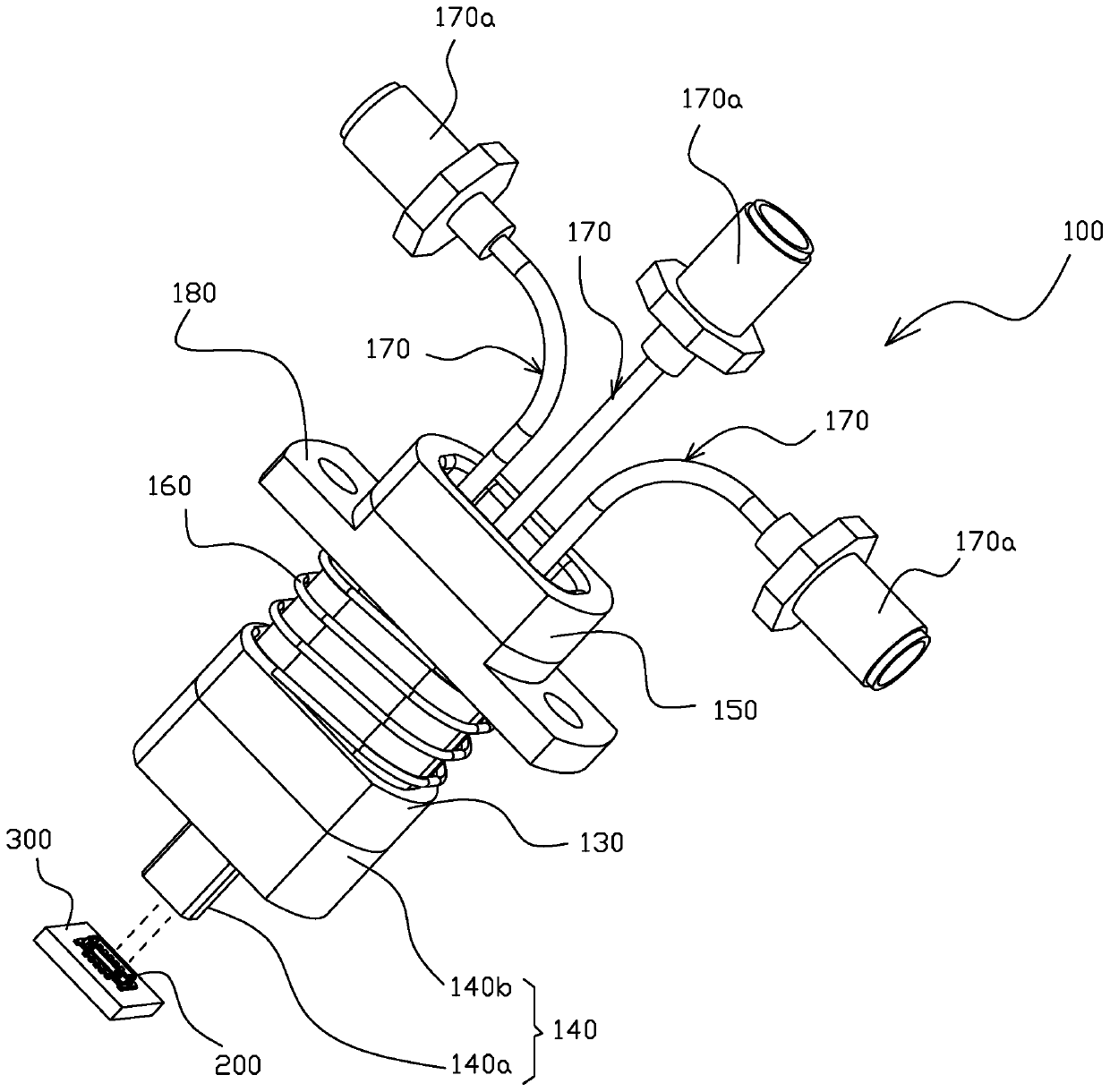
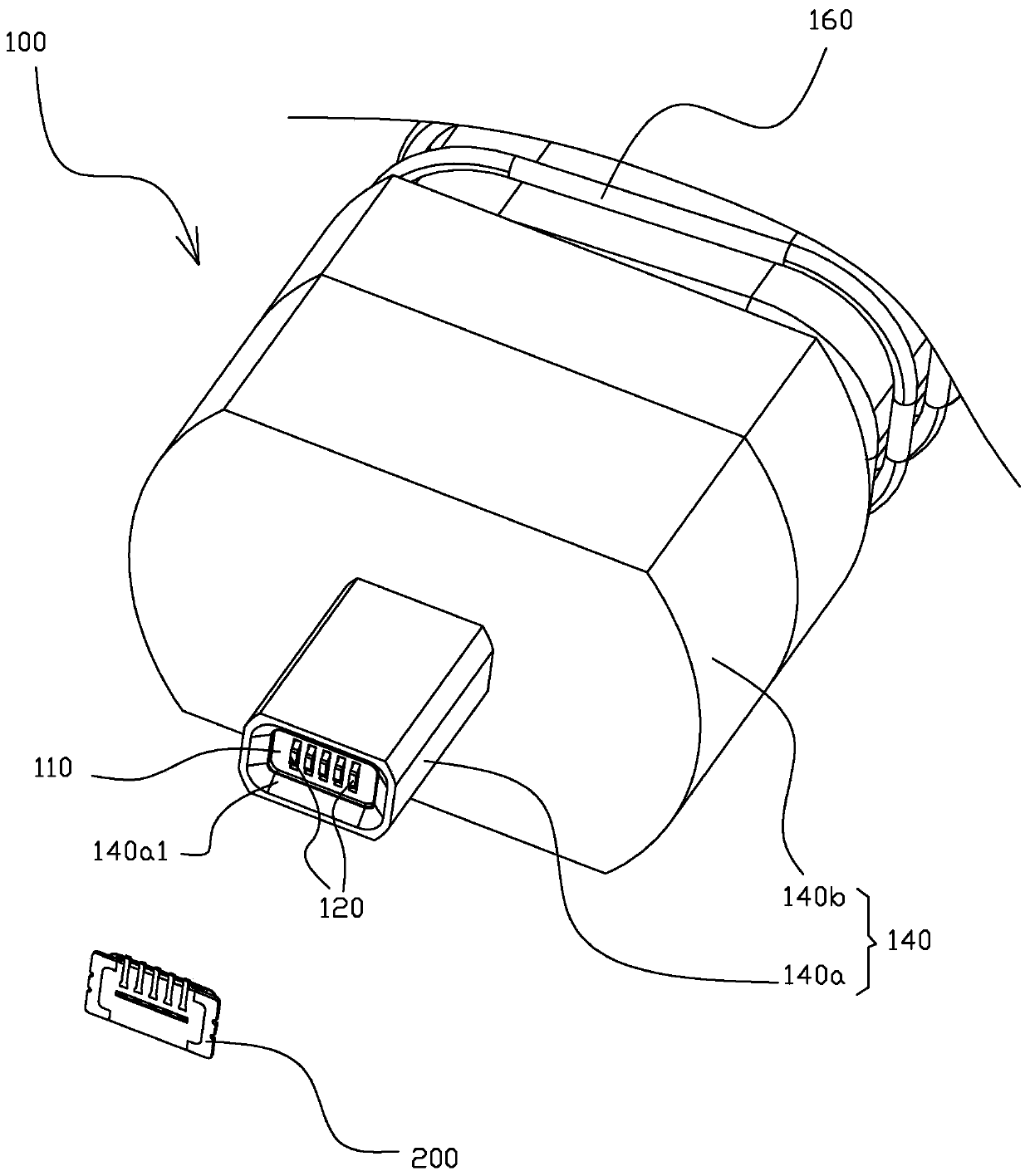
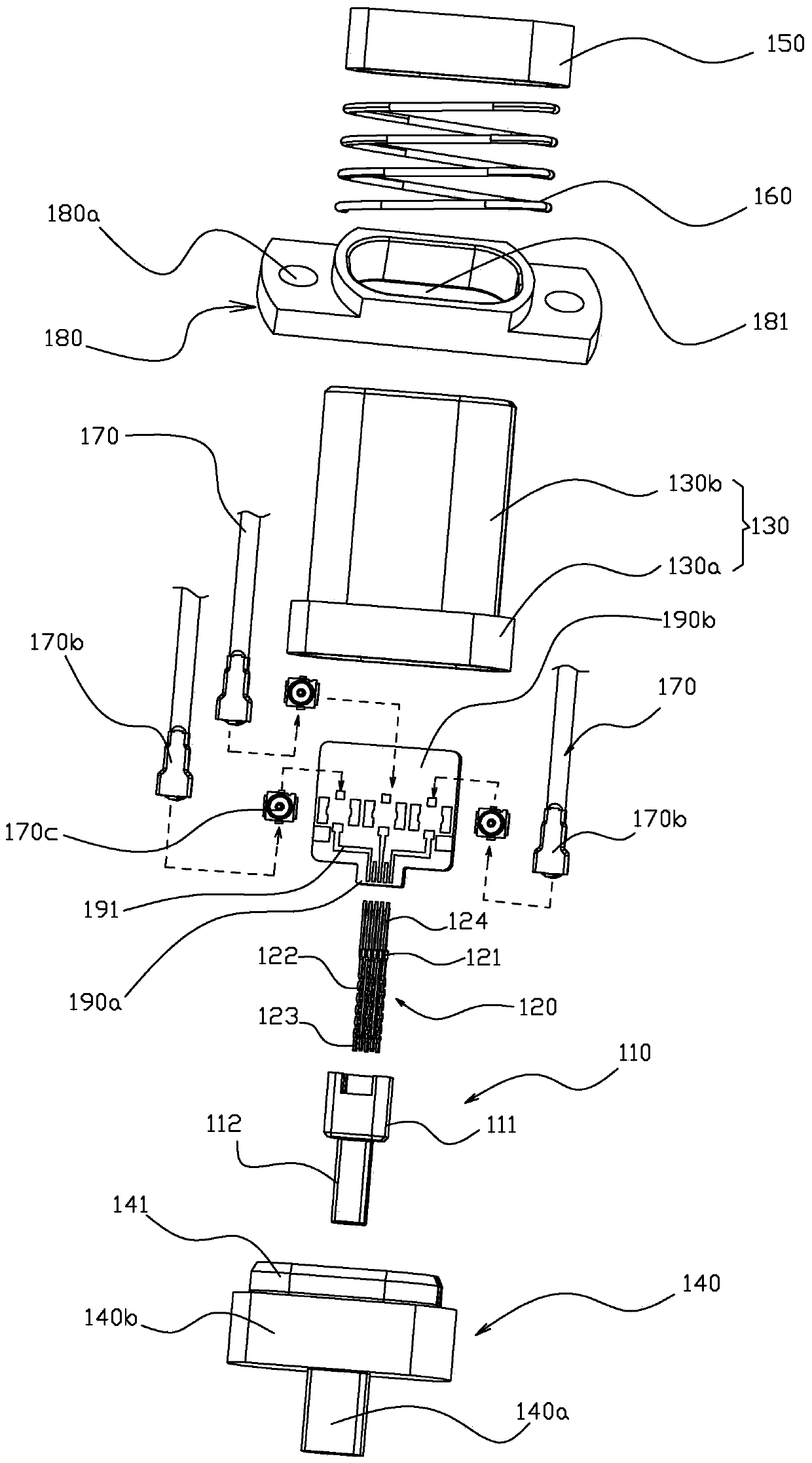
[0050] Such as Figure 1 to Figure 3 As shown, a multi-channel probe 100 in a preferred embodiment of the present invention is fitted and connected with a counterpart connector 200 installed on a printed circuit board of an electronic component as an object of measurement (the fitting direction is as follows: figure 1 shown), so that multiple high-frequency signals can be synchronously transferred from the tested printed circuit board to multiple cables, and connected to the detection equipment through the cables, so that the measured object can be accurately measured The detection purpose of multi-channel high-frequency characteristics.

[0051] The fitting connection mode between the probe 100 and its counterpart connector 200 can be referred to as shown in FIG. 4(a) and FIG. 4(b). On the opposite terminal 201 of the opposite connector 200 (refer to FIG. 4(b)), at the same time, the outer metal shielding (including the post, the conductive shell, etc.) around the contact po...


PUM


Abstract

The invention discloses a multi-channel probe, which comprises an inserting column, a main body, a plurality of conductive terminals, a conductive shell, a plurality of cables with coaxial joints, a circuit board, a flange body and a spring, wherein the main body is fixedly provided with the plurality of conductive terminals and is inserted into the inserting column; one end of the conductive shell is fixed on the inserting column, and the other end of the conductive shell is provided with a shaft sleeve part for stopping the inserting column from moving in the embedding direction; the circuitboard is provided with a plurality of lines to electrically connect the conductive terminals with the corresponding cables, and one side end of the circuit board is inserted into the main body; the flange body is used for being fixedly installed on a detection clamp and installed on the outer side of the conductive shell through a through hole of the flange body; and the spring is arranged between the inserting column and the flange body and is arranged at a position surrounding the outer side of the conductive shell to apply force to the inserting column in a direction far away from the flange body. Thus, the present invention enables a multi-channel probe of an electronic component to be measured with respect to a circuit board at a low cost.

Description

technical field [0001] The invention relates to a probe used for the determination of electronic components, especially for the test occasion of multi-channel signals. Background technique [0002] With the promotion of 5G applications and the gradual maturity of technology, communication terminals that can handle multiple frequencies are mainly used in communication systems, and multiple RF channels are required to perform signal transmission and other processing actions. Therefore, a corresponding number of devices connected to corresponding modules are arranged. Board connectors mounted on circuit boards. The corresponding configuration requirements of these connectors are miniaturization and high density. However, when performing high-frequency index performance testing on RF circuits, if using existing probes to confirm RF circuits inserted into such board-end connectors, it will be necessary Larger board space is not conducive to miniaturization. In addition, it is im...

Claims


Application Information

Patent Timeline
Patent Type & Authority Applications(China)
IPC IPC(8): G01R1/067
Inventor 赵善记
Owner ELECTRIC CONNECTOR TECH
Learn More