
Vehicle electromagnetic field emission intensity test system

A technology of emission intensity and test system, applied in the direction of electromagnetic field characteristics, etc., can solve the problem of inability to correlate vehicle operating conditions and detection data, etc.

Pending Publication Date: 2019-05-21
ZHENGZHOU YUTONG BUS CO LTD
View PDF0 Cites 5 Cited by
  • Summary
  • Abstract
  • Description
  • Claims
  • Application Information

AI Technical Summary

Problems solved by technology

[0007] The purpose of the present invention is to provide a vehicle electromagnetic field emission intensity testing system, which is used to solve the problem that the magnetic field intensity detection device in the prior art cannot correlate the vehicle working condition and detection data when testing the electromagnetic field emission intensity of the vehicle

Method used


Image

  • Vehicle electromagnetic field emission intensity test system
  • Vehicle electromagnetic field emission intensity test system

Examples


Embodiment Construction

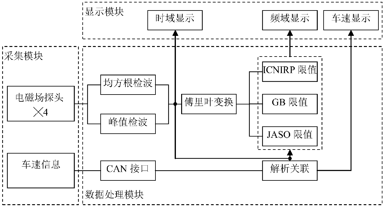
[0023] The purpose of the present invention is to provide a vehicle electromagnetic field emission intensity testing system, which is used to solve the problem that the magnetic field intensity detection device in the prior art cannot associate the vehicle working condition with the detection data when testing the electromagnetic field emission intensity of the vehicle.

[0024] To achieve the above object, the technical solution provided by the invention is:

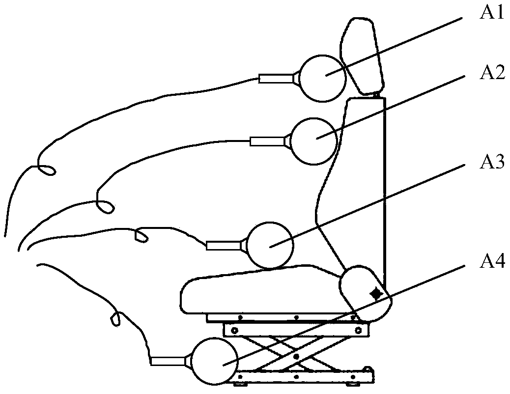
[0025] A vehicle electromagnetic field emission intensity testing system, comprising a data processing module, the data processing module is connected with at least one electromagnetic field probe for detecting the strength of the magnetic field; the data processing module is also connected with a vehicle speed acquisition module for obtaining the driving speed of the vehicle to be tested speed.

[0026] Embodiments of the present invention will be further described below in conjunction with the accompanying drawings. ...


PUM


Abstract

The invention provides a vehicle electromagnetic field emission intensity test system comprising a data processing module which is connected with at least one electromagnetic field probe used for detecting magnetic field intensity; and the data processing module is also connected with a vehicle speed acquisition module which is used for acquiring the running speed of a to-be-detected vehicle. According to the technical scheme provided by the invention, the vehicle speed acquisition module is connected to the data processing module of the vehicle electromagnetic field emission intensity test system to obtain the vehicle running speed information, so that the working condition of the vehicle is obtained, the running information of the vehicle is associated with the magnetic field intensity information, and the complete evaluation and analysis of the vehicle electromagnetic field emission intensity are realized.

Description

technical field [0001] The invention belongs to the technical field of vehicle performance detection, and in particular relates to a vehicle electromagnetic field emission intensity test system. Background technique [0002] With the development of science and technology, the application of electric energy is becoming more and more extensive, and the problem of electromagnetic pollution is becoming more and more serious. Electromagnetic pollution will not only interfere with the transmission of wireless communication signals between devices, but also affect the human body and cause harm to the human body. [0003] In order to reduce the harm caused by electromagnetic fields, various countries and organizations have formulated corresponding standards, such as my country's national standard GB 8702-2014 "Electromagnetic Environment Control Limits", and "Limiting Time-Varying Electric and Magnetic Fields" issued by the International Non-ionizing Radiation Protection Committee. ...

Claims


Application Information

Patent Timeline
Patent Type & Authority Applications(China)
IPC IPC(8): G01R29/08
Inventor 樊森李振山李东洋
Owner ZHENGZHOU YUTONG BUS CO LTD
Learn More