3D medical microscope

A microscope and medical technology, applied in the field of microscopes, can solve the problems of difficult focusing, limited switching magnification, and occupation of surgical space, etc., to achieve the effect of reducing the overall components and occupied space, simple and convenient operation, and great use benefits

Inactive Publication Date: 2019-05-21
INNOSERV
View PDF5 Cites 0 Cited by
  • Summary
  • Abstract
  • Description
  • Claims
  • Application Information

AI Technical Summary

Problems solved by technology

[0005] However, although the existing 3D stereoscopic surgical microscopes have used dual lenses to capture images, and can also switch the magnification and adjust the shooting angle, but the two lenses shoot directly downwards, so the magnification that can be switched is limited and easy. visual vignetting
More importantly, although the angle of shooting can be adjusted by swaying the lens, the oscillating lens also makes it difficult to focus, which in turn affects the alignment and

Method used


Image

  • 3D medical microscope
  • 3D medical microscope
  • 3D medical microscope

Examples


Embodiment Construction

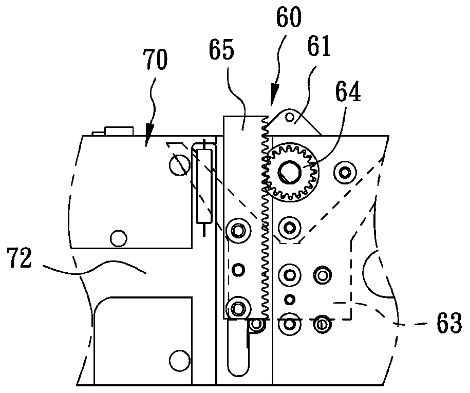
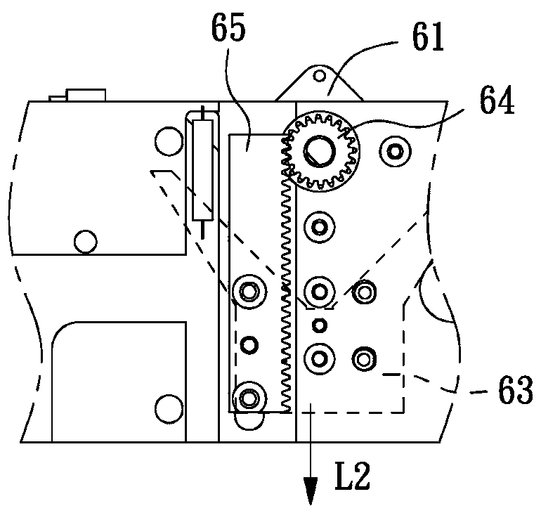
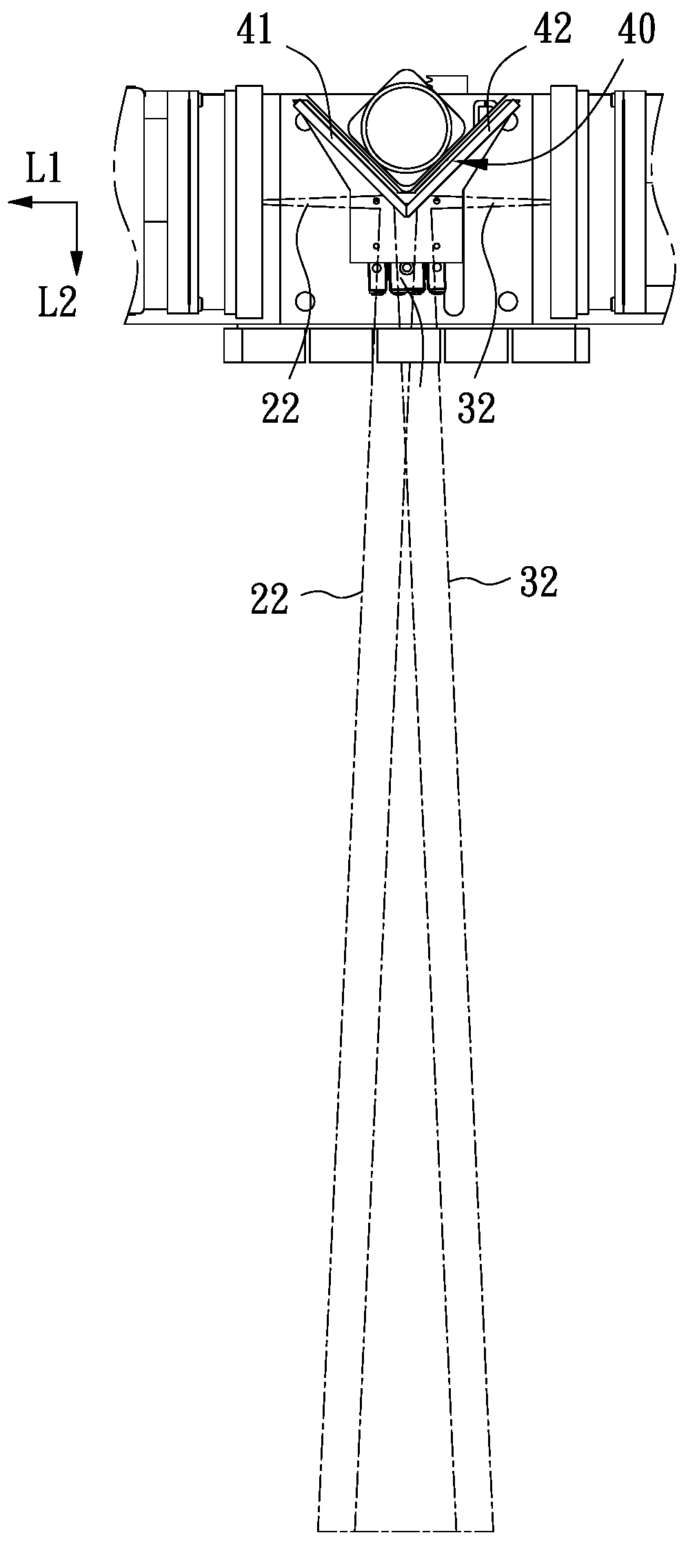
[0052] refer to figure 1 As shown, a preferred embodiment of the 3D medical microscope of the present invention includes a control unit 100 , a casing 10 , a first lens 20 , a second lens 30 , a reflection unit 40 and a drive unit 60 .

[0053] The control unit 100 is a control circuit and controls the required operation of the 3D medical microscope.

[0054] The casing 10 has an inner chamber 11 .

[0055] The first lens 20 is placed in the aforementioned inner chamber 11 and is electrically connected with the control unit 100 .

[0056] The second lens 30 is placed in the aforementioned inner chamber 11 and is electrically connected with the control unit 100 . The second lens 30 is located on the same horizontal axis L1 as the first lens 20 . In this embodiment, the first lens 20 and the second lens 30 are arranged oppositely, and both are internal zoom lenses, and a CCD (Charge-coupled Device, Charge-Coupled Device) 21, 31 is respectively arranged inside, respectively. ...


PUM


Abstract

The invention discloses a 3D medical microscope, which comprises a control unit for controlling the operation of the microscope, a shell with an internal chamber, and a first lens, a second lens, a reflecting unit and a driving unit which are arranged in the internal chamber. The first lens and the second lens are coaxially arranged; the reflecting unit is provided with a first reflecting surfaceand a second reflecting surface; the first reflecting surface is positioned between the first lens and the second lens, the first reflecting surface corresponds to the first lens and promotes an optical axis of the first lens to turn and project towards a vertical direction, and the second reflecting surface corresponds to the second lens and promotes an optical axis of the second lens to turn andproject towards the vertical direction. The driving unit drives the reflecting unit by a driving motor, so that the reflecting unit moves in the vertical direction.

Description

technical field [0001] The present invention relates to the field of microscope technology, in particular to a 3D microscope that can adjust the eye distance and eliminate visual vignetting in medicine, and can keep the entire picture clear and aligned during the process of switching magnification or lens shooting distance. medical microscope. Background technique [0002] In the past, microscopes used in medical operations were mainly provided with an objective lens group and at least two eyepiece lens groups at the front end of the body. The objective lens groups are connected, and the user can observe the images captured by the objective lens groups through each eyepiece lens group. [0003] However, because the lens in the objective lens group is a single and fixed structure, conventional microscopes can only provide stereoscopic images at the same depth, and cannot clearly present diseased tissues or blood vessels in some areas of the human body. As a result, doctors ...

Claims


Application Information

Patent Timeline
IPC IPC(8): G02B21/20G02B21/04G02B21/32G02B27/22
Inventor 吴智孟
Owner INNOSERV
Why Eureka
Try Eureka