Microscopic imaging system and method

A microscopic imaging and imaging technology, applied in microscopes, optics, instruments, etc., can solve the problems of poor imaging quality, stray halos and vignetting, and achieve the effect of eliminating stray halos and vignetting and improving imaging quality.

Pending Publication Date: 2021-03-26
SHANGHAI RUIYU BIOTECH
View PDF0 Cites 0 Cited by
  • Summary
  • Abstract
  • Description
  • Claims
  • Application Information

AI Technical Summary

Problems solved by technology

When using an optical objective lens to image a 96-well plate mainly used in biological culture, due to the surface tension of the liquid forming a meniscus and the light source irradiating the edge of the well, there will be stray halos and vignetting during imaging, and the imaging quality is poor.

Method used


Image

  • Microscopic imaging system and method
  • Microscopic imaging system and method
  • Microscopic imaging system and method

Examples


Embodiment Construction

[0029] The present invention will be further described in detail below in conjunction with the accompanying drawings and embodiments. It should be understood that the specific embodiments described here are only used to explain the present invention, but not to limit the present invention. In addition, it should be noted that, for the convenience of description, only some structures related to the present invention are shown in the drawings but not all structures.

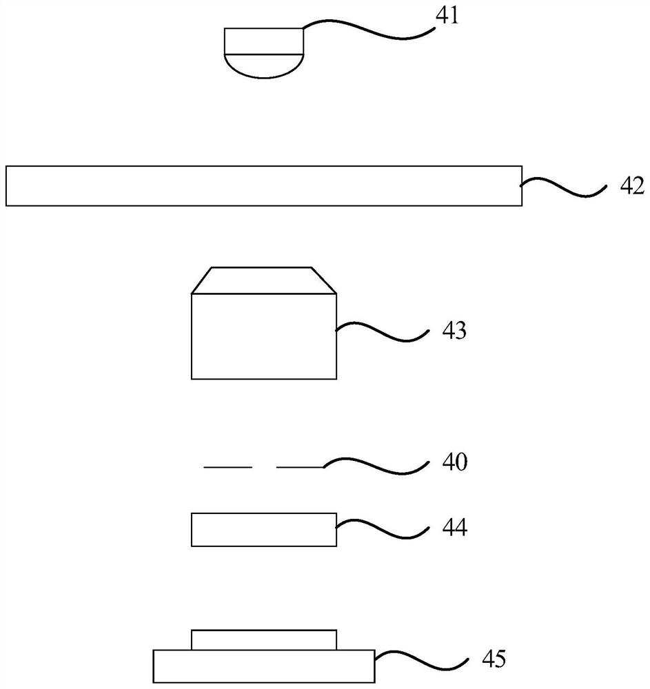
[0030] figure 1 For a schematic structural diagram of a microscopic imaging system provided by an embodiment of the present invention, refer to figure 1 , the microscopic imaging system includes an illumination light source 41, an imaging objective lens 43, an object stage 42 and an imaging unit 45. The illumination light source 41 provides an illumination light beam, and the object stage 42 is used to carry an orifice plate. After the illumination light beam is projected onto the sample on the orifice plate , th...


PUM


Abstract

The embodiment of the invention provides a microscopic imaging system and method. The microscopic imaging system comprises an illumination light source, an imaging objective lens, an objective table and an imaging unit; the illumination light source provides an illumination light beam, the objective table is used for bearing an orifice plate, and after the illumination light beam is projected to asample on the orifice plate, and the sample is imaged on the imaging unit by the imaging objective lens. The system also comprises a field diaphragm which is positioned on a light path between the imaging objective lens and the imaging unit. The embodiment of the invention provides the microscopic imaging system and method, so light beams converged by an imaging objective lens can be selectivelyshielded, stray light is shielded and removed, stray halo and dark corners caused by the edge of a concave liquid level are eliminated, and the imaging quality is improved.

Description

technical field [0001] The invention relates to microscopic imaging technology, in particular to a microscopic imaging system and method. Background technique [0002] As a microscopic observation device, the microscope is widely used in scientific research, industry and other fields. The traditional microscope light source consists of a condenser lens and an aperture, and its function is to concentrate the light on the specimen to be observed. When using an optical objective lens to image a 96-well plate mainly used in biological culture, due to the surface tension of the liquid forming a meniscus and the light source irradiating the edge of the well, there will be stray halos and vignetting during imaging, and the imaging quality is poor. . And if the light flux of the bright field light source is increased, a bright spot will be formed in the center. Contents of the invention [0003] Embodiments of the present invention provide a microscopic imaging system and metho...

Claims


Application Information

Patent Timeline
Patent Type & Authority Applications(China)
IPC IPC(8): G02B21/36G02B21/00G02B5/00
CPCG02B5/005G02B21/00G02B21/361
Inventor 张晓佳
Owner SHANGHAI RUIYU BIOTECH
Why Eureka
Try Eureka