

A clamping device for a relay
The technology of a relay and a clamping mechanism is applied in the field of the clamping device of the relay, which can solve the problems such as the sliding of the relay, the inability to use the clamping device, the complicated installation and disassembly, etc., and achieve the effects of stable and reliable installation, improved work efficiency and simple structure.
Active Publication Date: 2022-05-31
广东求精电气有限公司
View PDF9 Cites 0 Cited by
- Summary
- Abstract
- Description
- Claims
- Application Information
AI Technical Summary
Problems solved by technology
[0002] The existing box clamping device is generally movable clamped on the guide rail, and the guide rail is provided in the cabinet, and the integrated device is clamped on the guide rail. However, this kind of card cannot be used in some specific positions. Connecting device, and the clipping device also has the situation that the clipping is not reliable
[0003] Due to the different on-site environments, sometimes it is necessary to use different types of relays, and sometimes they need to be combined for use. Since there is no fixation between adjacent relays, when the vibration is large, the existing spring slide buckle Components connected to the rails can easily cause the relay to slip or fall off, causing the relay to deviate from its original position
In addition, it is easy to cause deformation of the wire connected to the relay, and even cause the wire to fall off, and the adjacent relay is not fixed, and the installation and removal are very cumbersome
Method used
View moreImage
Smart ImageViewing Examples

Examples
Embodiment Construction
[0022] In the accompanying drawings of the embodiments of the present invention, the same or similar reference numerals correspond to the same or similar components; in the description of the present invention
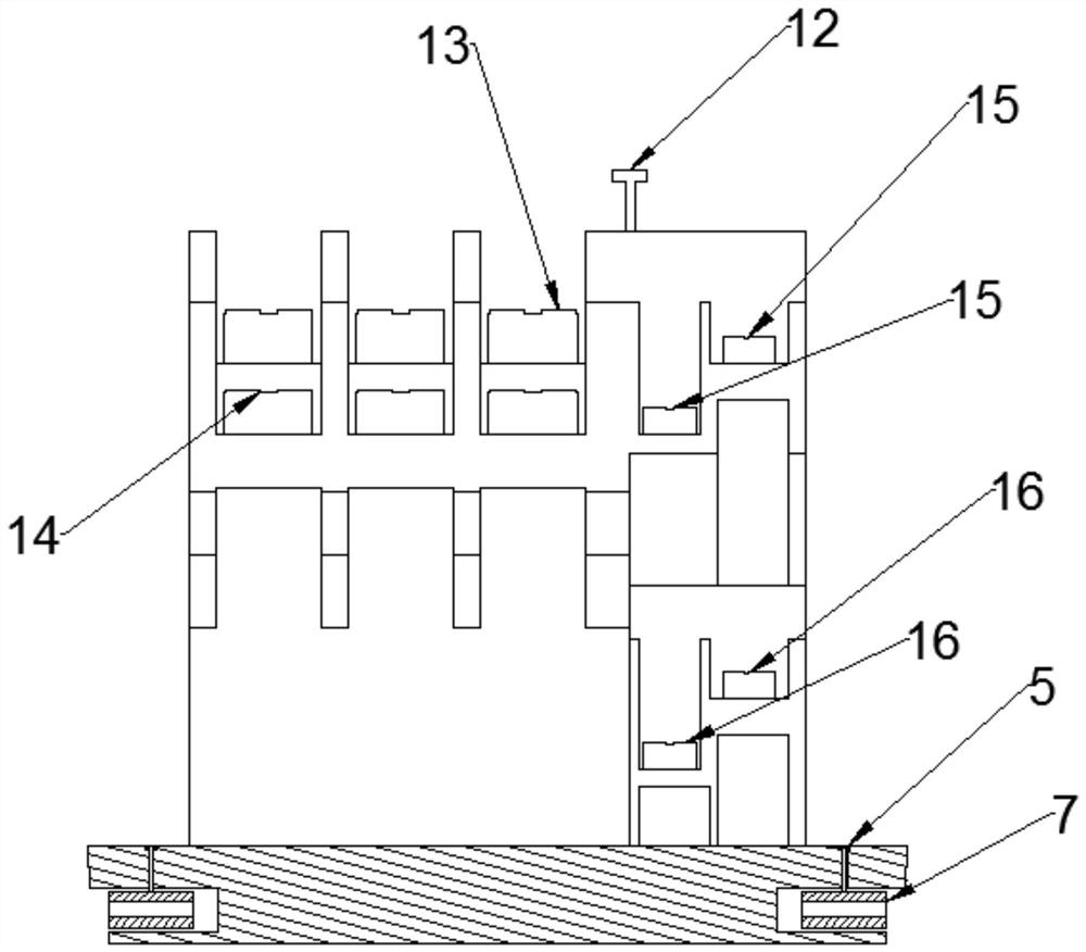
[0024] The base is provided with a plurality of groups of clamping mechanisms, and each group of the clamping mechanisms is symmetrically and parallelly arranged on the bottom
[0025] The top surface of the edge portion is provided with a nut groove, and the nut groove is arranged coaxially with the through hole. Specifically, the
[0028] The side of the guide rail 10 facing the base 1 is symmetrically provided with the first protrusions 11, and each of the first protrusions
Login to View More PUM
 Abstract
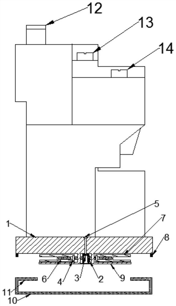
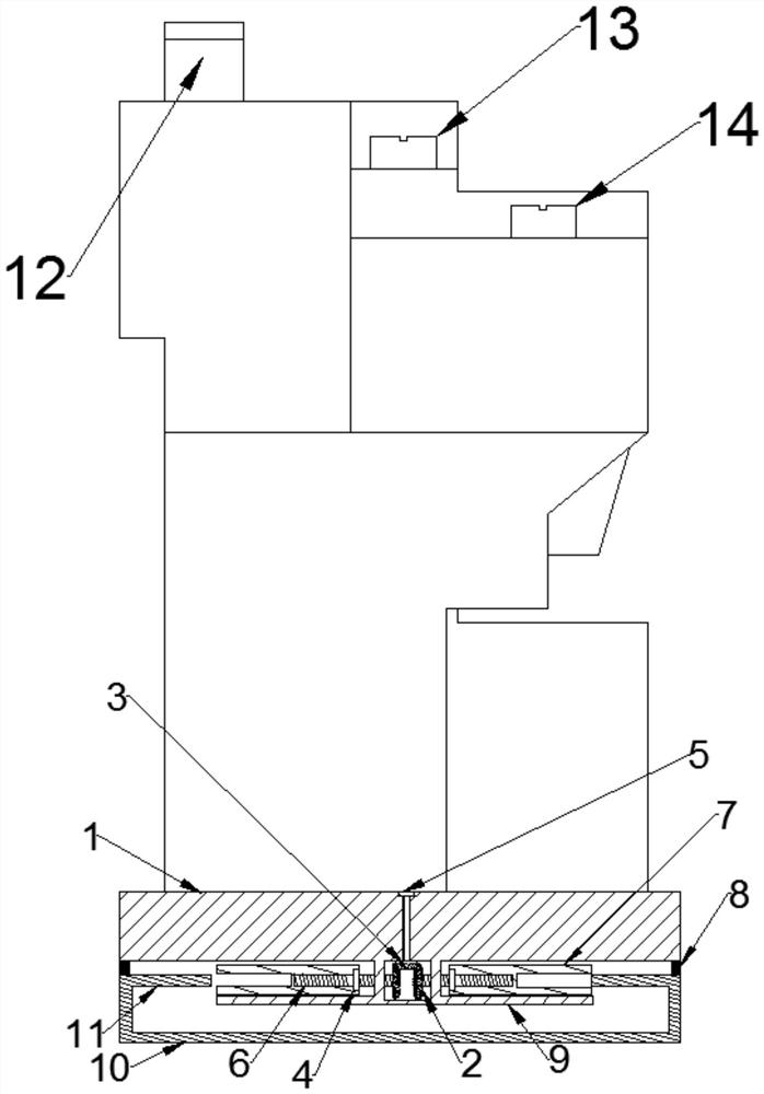
The invention provides a clamping device for a relay, which includes a relay and a guide rail. The relay includes a base and a relay body. The relay body is arranged on the top of the base and the two are integrally formed. The bottom protrudes symmetrically. There are several ladder shapes on the relay body, and each ladder shape is not set on the same level. The edge of the base is provided with a clamping mechanism that can be clamped with the guide rail. The clamping mechanism includes a pin rod, The gear chamber, the clamping chamber and the abutting piece are provided with a through hole on the edge, and a pin rod is provided in the through hole and communicated with the gear chamber. The gear chamber is respectively provided with a first bevel gear and two second bevel gears, and the pin One end of the rod is rotatably connected to the top of the base, the other end is fixedly connected to the first bevel gear, and two second bevel gears are meshed symmetrically on both sides of the first bevel gear respectively. The clamping device of the invention is simple in structure, stable and reliable, and improves the clamping effect of the clamping device.
Description
A relay clipping device technical field [0001] The present invention relates to the field of electrical equipment accessories, in particular to a latching device for a relay. Background technique [0002] The existing box body clipping device is generally movably clipped on the guide rail, by being provided with a guide rail in the box, and using The one-piece device is snapped on the guide rail, but this snapping device cannot be used in some specific positions, and the snap The device also has a situation where the clamping is not reliable. [0003] Due to the difference in the field environment, sometimes different types of relays need to be used, and sometimes they need to be combined Up to use, because there is no fixed between adjacent relays, when the vibration environment is large, the existing through the spring sliding The device that is clamped on the guide rail can easily cause the relay to slip or fall off, causing the relay to deviate from its original po...
Claims
Login to View More Application Information
Patent Timeline
 Patent Type & Authority Patents(China)
IPC IPC(8): H01H50/02H01H50/04
Inventor 赵成雷陈正茂张传荣
Owner 广东求精电气有限公司