
Vehicle-mounted constant force fire fighting winch

A vehicle-mounted, constant-force technology that is applied to hoisting devices, clockwork mechanisms, etc., and can solve problems such as increased manufacturing and use costs, increased power, and increased winch volume

Pending Publication Date: 2019-05-24
JIEDA FIRE PROTECTION VEHICLE EQUIP CO LTD SUZHOU CITY
View PDF2 Cites 0 Cited by
  • Summary
  • Abstract
  • Description
  • Claims
  • Application Information

AI Technical Summary

Problems solved by technology

[0005] The technical information of all constant force capstans can be seen in the published Chinese patent literature, typical as invention patent application publication number CN106081962A recommends "a kind of constant force constant speed electric winch" and invention patent application publication number CN109399477A provides " self-adaptive Two-way large-angle double-drum light-duty constant force winch" is not limited to the above-mentioned exemplified patents. The steel wire rope wound on the drum varies with the change of the radius of the complex, but the effective length of the wire rope depends to a certain extent on the diameter of the drum (also called "winch" or "winch drum", the same below) and Length, specifically, the larger the diameter (outer diameter) of the reel and the longer the length, the relatively longer the effective length of the wire rope. In view of this, the length of the wire rope (that is, the traction rope) of the aforementioned patent is limited, unless the reel The diameter and / or length of the drum increase, but increasing the diameter and length of the drum will produce the following disadvantages: one is to increase the power of the power device that drives the drum to work, such as the power of the motor; the other is to significantly increase the volume of the entire winch; The third is to increase the cost of manufacturing and use

Method used


Image

  • Vehicle-mounted constant force fire fighting winch
  • Vehicle-mounted constant force fire fighting winch
  • Vehicle-mounted constant force fire fighting winch

Examples


Embodiment Construction

[0023] In order to understand the technical essence and beneficial effects of the present invention more clearly, the applicant will describe in detail the following examples, but the descriptions of the examples are not intended to limit the solutions of the present invention. Equivalent transformations that are only formal but not substantive should be regarded as the scope of the technical solution of the present invention.

[0024] In the following descriptions, all the directional or azimuth concepts such as up, down, left, right, front and back are based on figure 2 The current position is a reference, so it cannot be understood as a special limitation on the technical solution provided by the present invention.

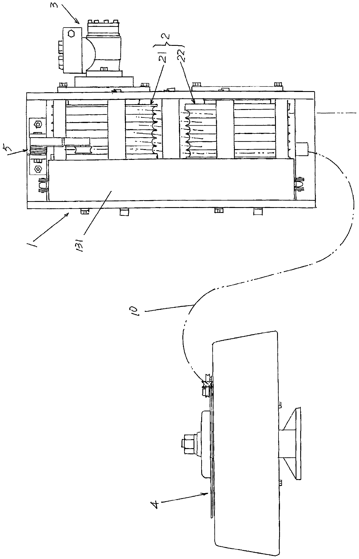
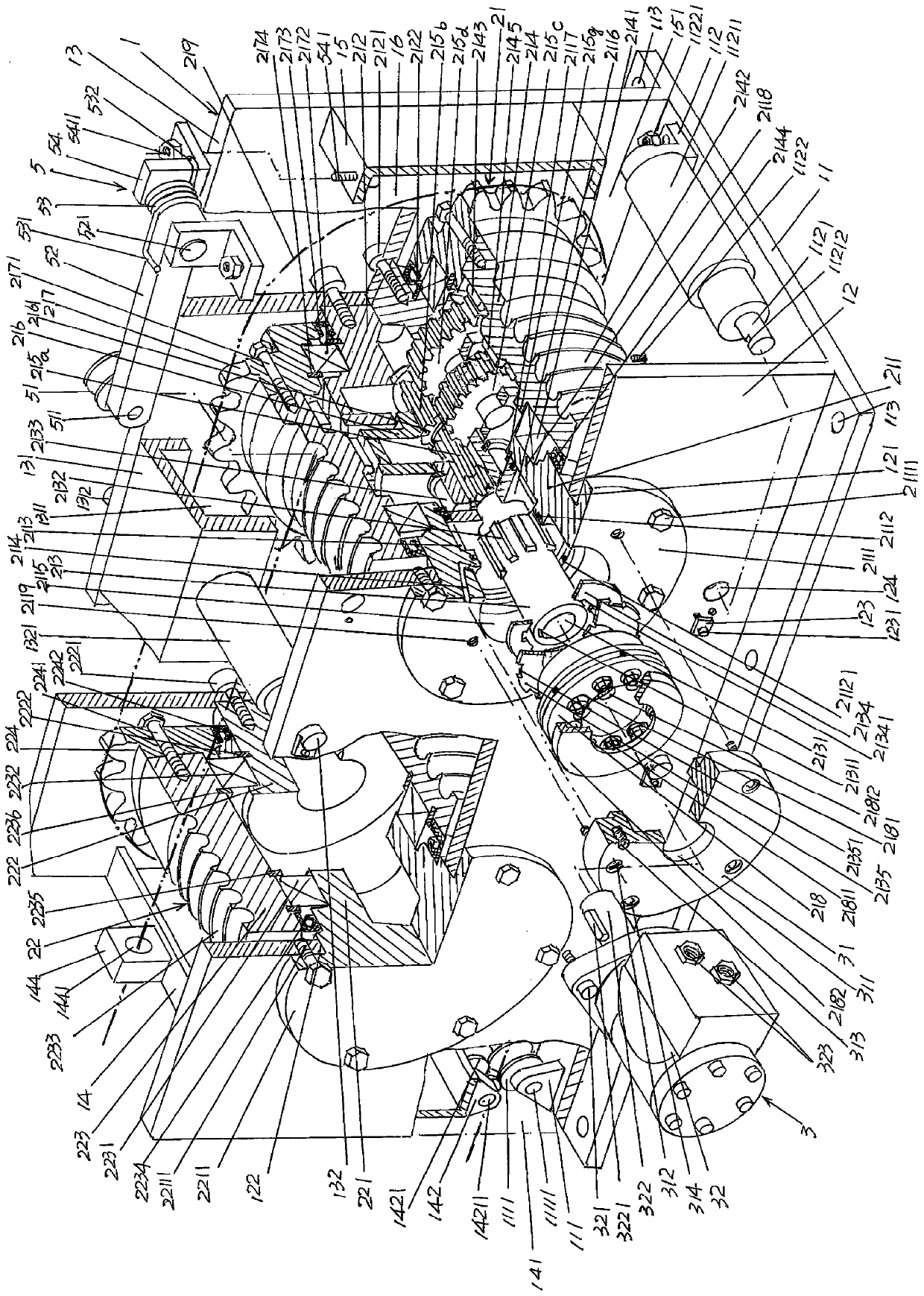
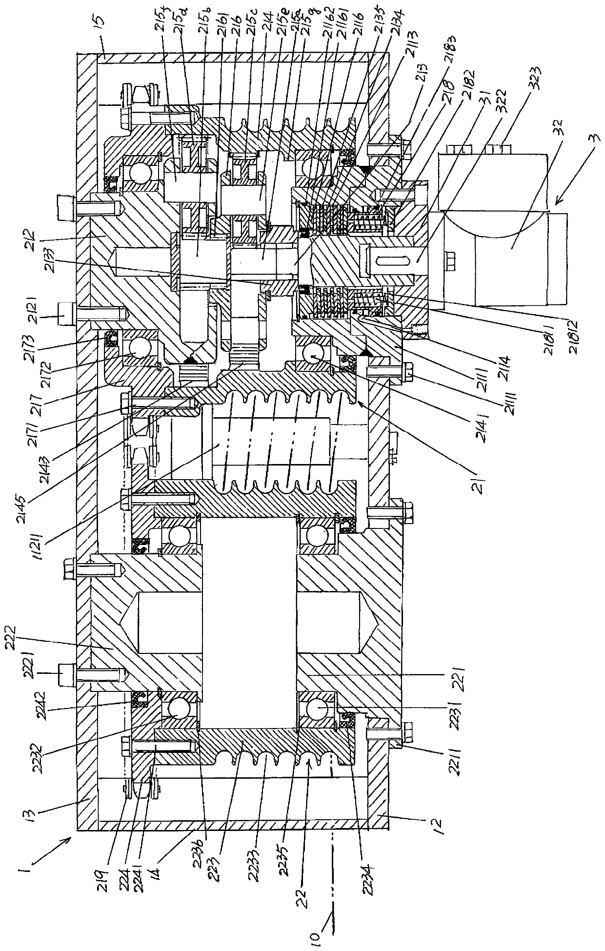
[0025] See figure 1 , shows a base 1, the base 1 is fixed on the fire truck in use, such as fire trucks, lighting fire trucks, smoke exhaust fire trucks, etc. On various fire trucks with multiple functions of the same class; a retractable rope mechanism 2 (a...


PUM


Abstract

The invention provides a vehicle-mounted constant force fire fighting winch, and belongs to the technical field of fire fighting facilities. The vehicle-mounted constant force fire fighting winch comprises a base, a rope collecting and releasing mechanism and a reel driving mechanism, the base is fixed on a fire fighting truck in use, the rope collecting and releasing mechanism is used for collecting or releasing a traction rope and arranged on the base, the reel driving mechanism is arranged on the base and is in transmission connection with the rope collecting and releasing mechanism, and the traction rope is wound on the rope collecting and releasing mechanism in a single-layer flat laying state. The vehicle-mounted constant force fire fighting winch is characterized by further comprising a traction rope storing mechanism used for storing the traction rope, wherein the traction rope storing mechanism is arranged at a position,corresponding to the rope collecting and releasing mechanism, of the fire fighting truck; and the redundant part of the traction rope generated after the traction rope is wound on the rope collecting and releasing mechanism in the single-layer flat laying state is stored in the traction rope storing mechanism. Traction failure is avoided, and the traction requirements for long-distance objects can be met without increasing the diameter and / or the length of a driving reel and a driven reel.

Description

technical field [0001] The invention belongs to the technical field of fire-fighting facilities, and in particular relates to a vehicle-mounted constant force fire-fighting winch. Background technique [0002] The fire winch is an indispensable facility for emergency rescue fire trucks. Because it can play an important role in emergency rescue, it is usually equipped with equipment fire trucks, lighting fire trucks, smoke exhaust fire trucks, and firefighting, rescue, anti-riot, etc. Various types of fire fighting vehicles with multiple functions. [0003] The fire winch in the prior art usually uses an electric winch and the steel wire rope used as the traction rope is wound on the drum in a laminated form (also called "laminated state"). Take a reel, a steel wire rope with a diameter of 13mm and a length of 30m, and four layers of rewinding (that is, "rewinding", the same below) on the reel as an example. Since the rated output power and torque of the motor are fixed, the...

Claims


Application Information

Patent Timeline
Patent Type & Authority Applications(China)
IPC IPC(8): B66D1/08B66D1/36B66D1/74
Inventor 张建明
Owner JIEDA FIRE PROTECTION VEHICLE EQUIP CO LTD SUZHOU CITY
Learn More