Indoor floor constant-temperature system

A constant temperature system and floor technology, applied in lighting and heating equipment, floors, fluid heaters, etc., can solve problems such as slippery floors and water stains, and achieve the effect of improving safety and friction

Active Publication Date: 2019-05-28
深圳百川装饰集团有限公司
View PDF5 Cites 4 Cited by
  • Summary
  • Abstract
  • Description
  • Claims
  • Application Information

AI Technical Summary

Problems solved by technology

However, since the floor of the bathroom is usually stained with water after washing, the floor is relatively slippery.

Method used


Image

  • Indoor floor constant-temperature system
  • Indoor floor constant-temperature system
  • Indoor floor constant-temperature system

Examples


Embodiment Construction

[0041] The present invention will be described in further detail below in conjunction with the accompanying drawings.

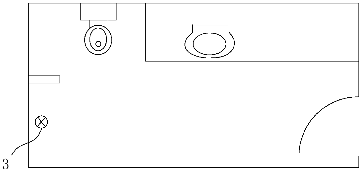
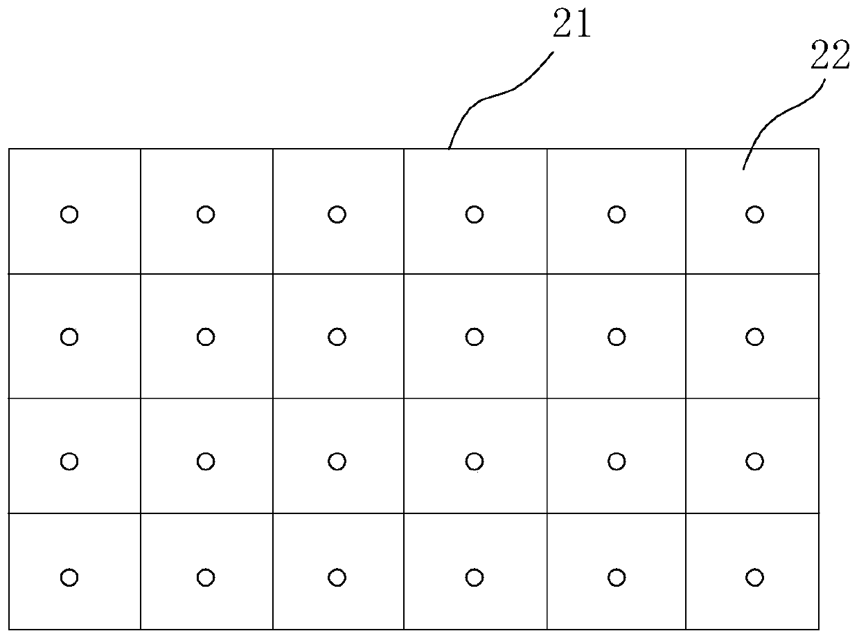
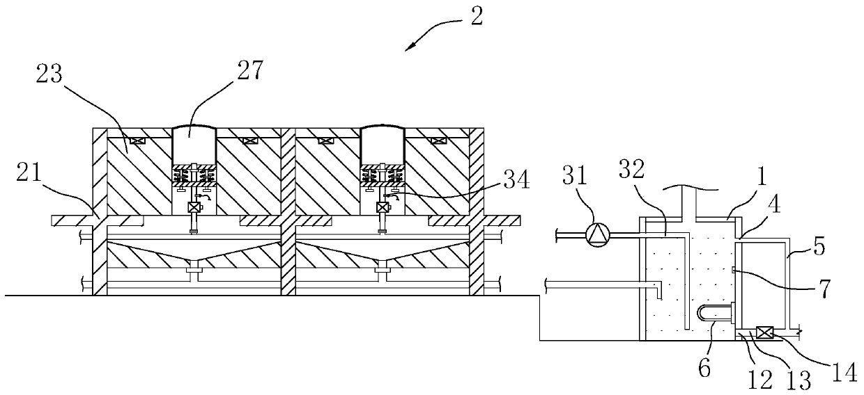
[0042] combine figure 1 and image 3 As shown, an indoor floor constant temperature system includes a pyroelectric infrared sensor, a water storage tank 1, an anti-skid assembly 2 and a controller.

[0043] The pyroelectric infrared sensor is installed on the wall of the indoor bathroom. In this application, there are multiple pyroelectric infrared sensors. Covering the indoor bathroom, users can be detected in any corner of the indoor bathroom.

[0044]The water storage tank 1 is arranged outside the indoor bathroom, and the level of the water storage tank 1 is lower than the level of the floor of the indoor bathroom. The water storage tank 1 is connected to the floor drain 3 of the indoor bathroom through a water storage pipe, so that when bathing in the indoor bathroom, the water body passes through The floor drain 3 can directly enter the water storage...


PUM


Abstract

The invention discloses an indoor floor constant-temperature system. The technical scheme of the system is characterized in that a floor body is installed in each installation cell, at least one air bag installing groove is formed in each floor body, an air bag support table is installed in each air bag installing groove, an air bag body is fixed on each air bag support table, a water filling headcommunicated with the corresponding air bag body is arranged on each air bag support table, a water inlet pipe network communicated with each installing cell is arranged in a support base, a water inlet hose connected with each water filling head is arranged on the water inlet pipe network, a micro water pump is installed on the water inlet pipe network, a pipeline extending into a water storagetank is connected onto the micro water pump, a first electromagnetic valve is installed in each installing cell and located on the water inlet hose, and a liquid pressure sensor is installed between the first electromagnetic valve and the water filling head; a controller receives a human body sensing signal output by a pyroelectric infrared sensor and controls the micro water pumps and the first electromagnetic valves to start to fill the air bag bodies with water to reach a first preset hydraulic pressure value.

Description

technical field [0001] The invention relates to the technical field of indoor bathroom control, in particular to an indoor floor constant temperature system. Background technique [0002] At present, the bathroom has become an important part of people's life, and people use the bathroom almost every day. But, because the floor of the bathroom is usually stained with water on the surface after washing, the floor is relatively slippery. When people are walking, due to the reduced friction between the soles of the feet and the floor of the bathroom, it is easy to cause people to fall. Therefore, there is a certain improvement for the floor of the bathroom. Contents of the invention [0003] In view of the deficiencies in the prior art, the purpose of the present invention is to provide an indoor floor constant temperature system, which can improve the anti-slip effect to a certain extent. [0004] Above-mentioned technical purpose of the present invention is achieved throug...

Claims


Application Information

Patent Timeline
Patent Type & Authority Applications(China)
IPC IPC(8): E04F15/18E04F15/02F24H1/20F24H9/20
Inventor 李东荣吴晓敏
Owner 深圳百川装饰集团有限公司
Why Eureka
Try Eureka