Temperature-controlled automatic energy-saving water mixing valve

A technology of temperature-controlled water mixing valves, applied in valve details, multi-way valves, valve devices, etc., can solve problems such as low efficiency, waste of water resources, waste of cold and hot water, etc.

Active Publication Date: 2019-05-28
广东美厨世家热能科技有限公司
View PDF6 Cites 6 Cited by
  • Summary
  • Abstract
  • Description
  • Claims
  • Application Information

AI Technical Summary

Problems solved by technology

[0002] The water mixing valve is a valve for mixing hot and cold water. By connecting the cold water pipe and the hot water pipe to the water mixing valve, the switching flow of the water mixing valve is manually adjusted to achieve the mixing of cold and hot water, thereby obtaining warm water; the existing The water mixing valve needs to be manually adjusted by the user when the water temperature is suitable. This method is not only cumbersome and inefficient, but also wastes a certain amount of time when the user adjusts the water mixing valve. A large amount of hot and cold water is not conducive to the conservation of water resources, thereby increasing the cost of using hot and cold water; in addition, when the existing domestic water heaters take water, it usually takes a certain amount of heating time. Before that, all the hot water flowing out of the pipe is Cold water, so users will not only waste water resources when taking hot water, but also need to check the water temperature in the hot water pipe at all times to avoid scalding when the hot water flows out; in addition, the existing mixing valve , since the early stage of water mixing will be affected by the cold water pipe, it will also affect the efficiency of the water mixing valve when mixing water to a certain extent; in summary, there are defects

Method used


Image

  • Temperature-controlled automatic energy-saving water mixing valve
  • Temperature-controlled automatic energy-saving water mixing valve
  • Temperature-controlled automatic energy-saving water mixing valve

Examples


Embodiment Construction

[0013] The present invention will be further explained below in conjunction with the drawings and embodiments:

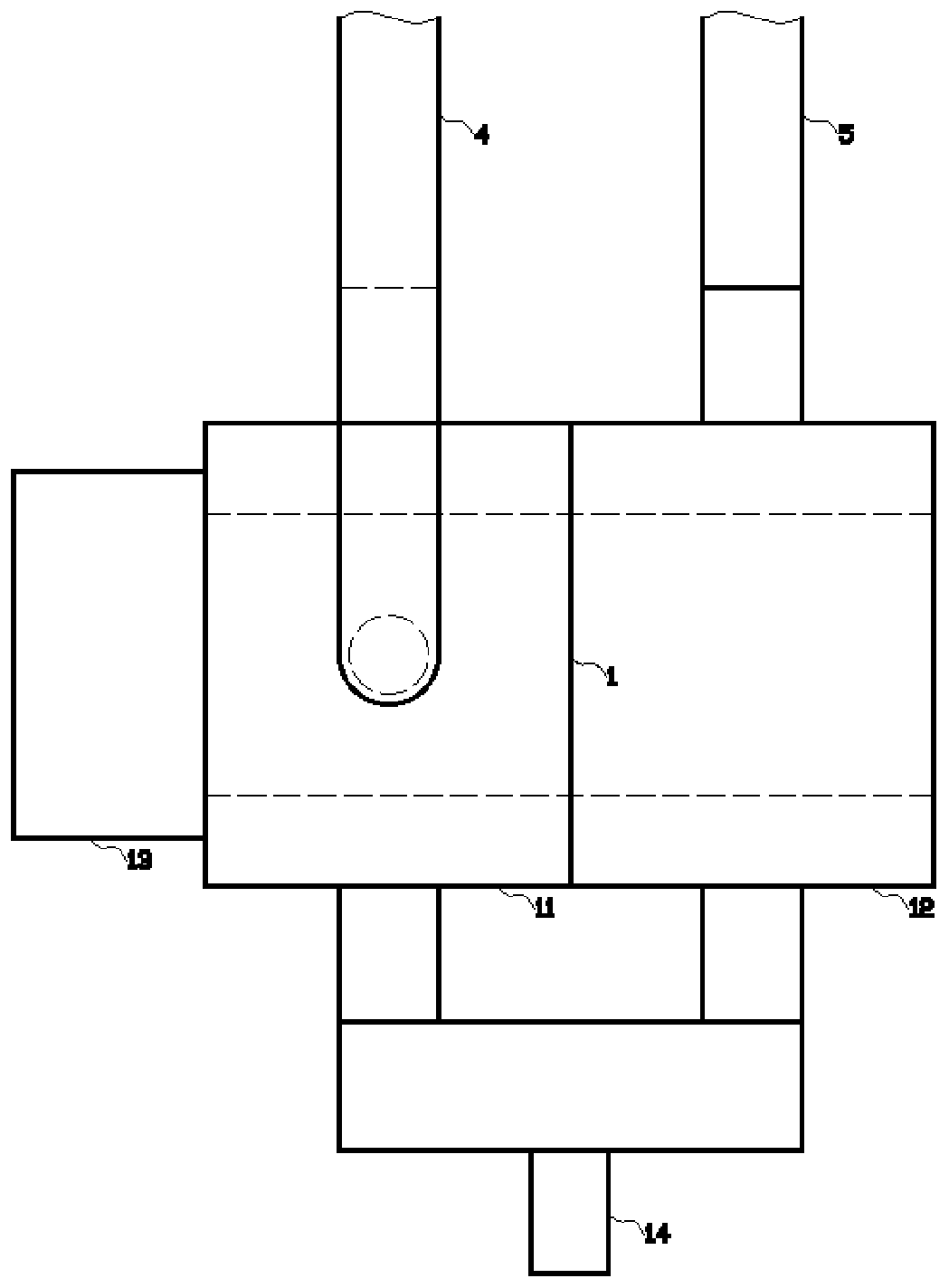
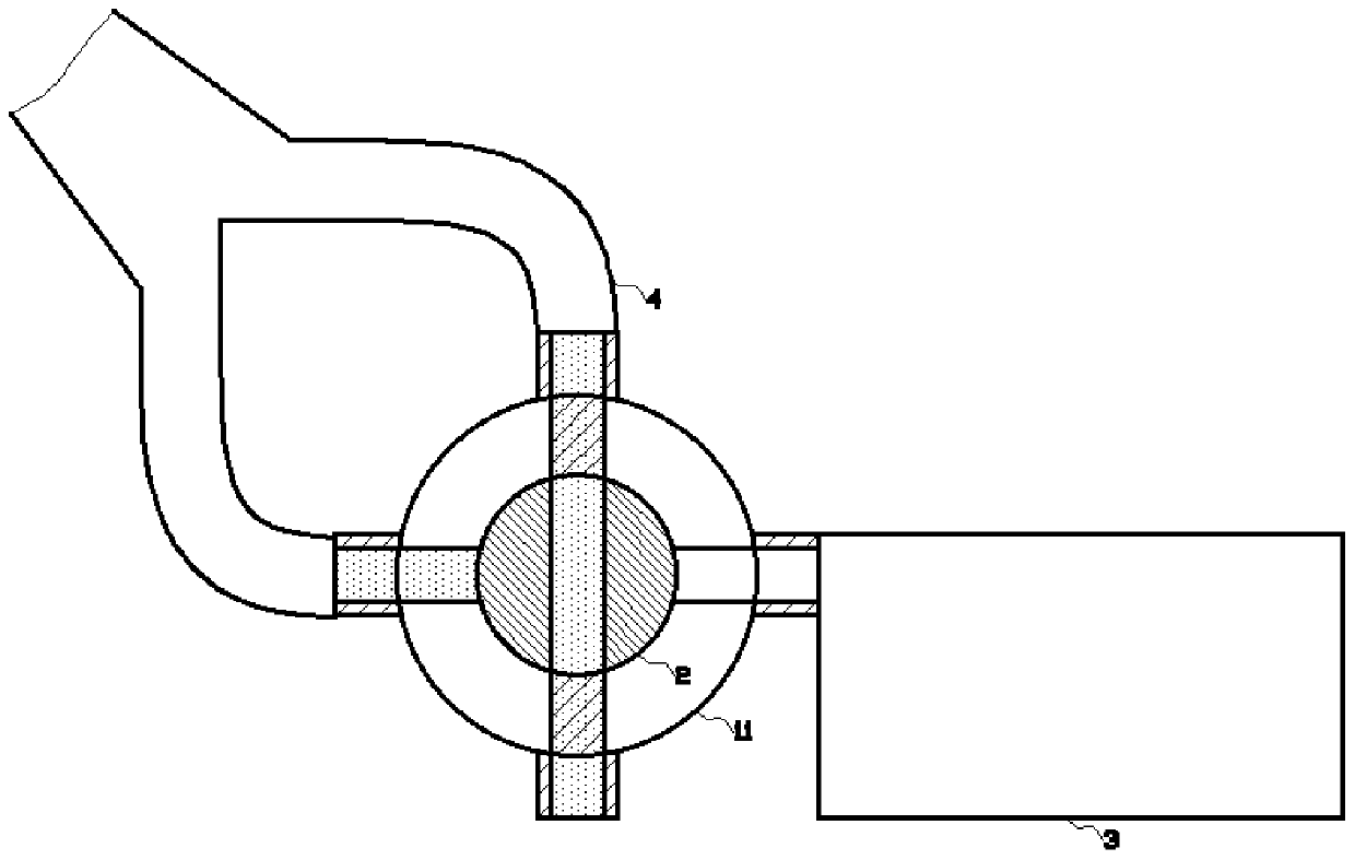
[0014] Such as figure 1 , figure 2 , image 3 , Figure 4 As shown in the example, the temperature-controlled automatic energy-saving water mixing valve detects the water temperature of the hot water pipe, so that when the cold water is discharged in the early stage, the cold water is drained to the storage tank for storage, and when the water temperature rises, it is opened at the same time The opening of the cold and hot water pipe flows out through the water mixing valve to obtain warm water. It includes a water mixing module 1, a regulating module 2, a water storage tank 3, a hot water pipe 4 and a cold water pipe 5; the shape of the water mixing module 1 In a cylindrical shape, the water mixing module 1 is provided with a transverse cylindrical cavity inside, the water mixing module 1 includes a cold water valve 12 and a hot water valve 11, the cold water valve 1...


PUM


Abstract

The invention provides a temperature-controlled automatic energy-saving water mixing valve. The temperature-controlled automatic energy-saving water mixing valve comprises a water mixing module, an adjustment module, a water storage tank, a hot water tank and a cold water pipe, the water mixing module comprises a cold water valve and a hot water valve, the adjustment module comprises a reversing shaft, symmetrically runners are arranged in the reversing shaft, a temperature-controlled switch is arranged on the extending side of the adjustment module, an electric rotating device is arranged onthe temperature-controlled switch, and a water drainage pipe is arranged on the water storage tank. According to the temperature-controlled automatic energy-saving water mixing valve, the water temperature detection is conducted on the hot water pipe, so that the cold water is drained into the water storage tank to be stored before the discharge of the cold water at the early stage, after the rising of the water temperature, openings of the cold and hot water pipes are opened simultaneously, the water flows out through the water mixing valve, and the warm water is obtained accordingly.

Description

Technical field [0001] The invention relates to the field of water valve equipment, in particular, to an energy-saving water mixing valve. Background technique [0002] The mixing valve is a valve for mixing cold and hot water. By connecting the cold water pipe and the hot water pipe to the mixing valve, manually adjust the on-off flow of the mixing valve to achieve the mixing of cold and hot water, thereby obtaining warm water; The water mixing valve needs to be manually adjusted by the user when the water temperature is appropriate. This method is not only cumbersome to use, and low efficiency, but also wastes a certain amount of time when the user adjusts the water mixing valve. The amount of hot and cold water is not conducive to saving water resources, thereby increasing the cost of using cold and hot water; in addition, the existing domestic water heaters usually require a certain heating time when taking water. Before that, the hot water pipes are all flowing out. Cold wa...

Claims


Application Information

Patent Timeline
Patent Type & Authority Applications(China)
IPC IPC(8): F16K11/085F16K31/04F16K31/05F16K41/02F24H9/20
Inventor 李晨阳
Owner 广东美厨世家热能科技有限公司
Why Eureka
Try Eureka