Zerofriction inertia step scanister, control method, idem spot scanning double probe microscope

A step-scanning, frictionless technology, applied in the field of scanning dual-probe microscopes at the same point, can solve the problems of low positioning accuracy, interference of positioning accuracy, complicated control, etc., and achieve the effects of low cost, high positioning accuracy and small size

Inactive Publication Date: 2008-07-23
UNIV OF SCI & TECH OF CHINA
View PDF0 Cites 6 Cited by
  • Summary
  • Abstract
  • Description
  • Claims
  • Application Information

AI Technical Summary

Problems solved by technology

[0004] The purpose of the present invention is to solve the interference of the above-mentioned friction force on the positioning accuracy, provide a frictionless inertial step scanner with high positioning accuracy and its control method

Method used


Image

  • Zerofriction inertia step scanister, control method, idem spot scanning double probe microscope
  • Zerofriction inertia step scanister, control method, idem spot scanning double probe microscope

Examples


Embodiment 1

[0046] Embodiment 1: Frictionless inertial step scanner with built-in tensioner

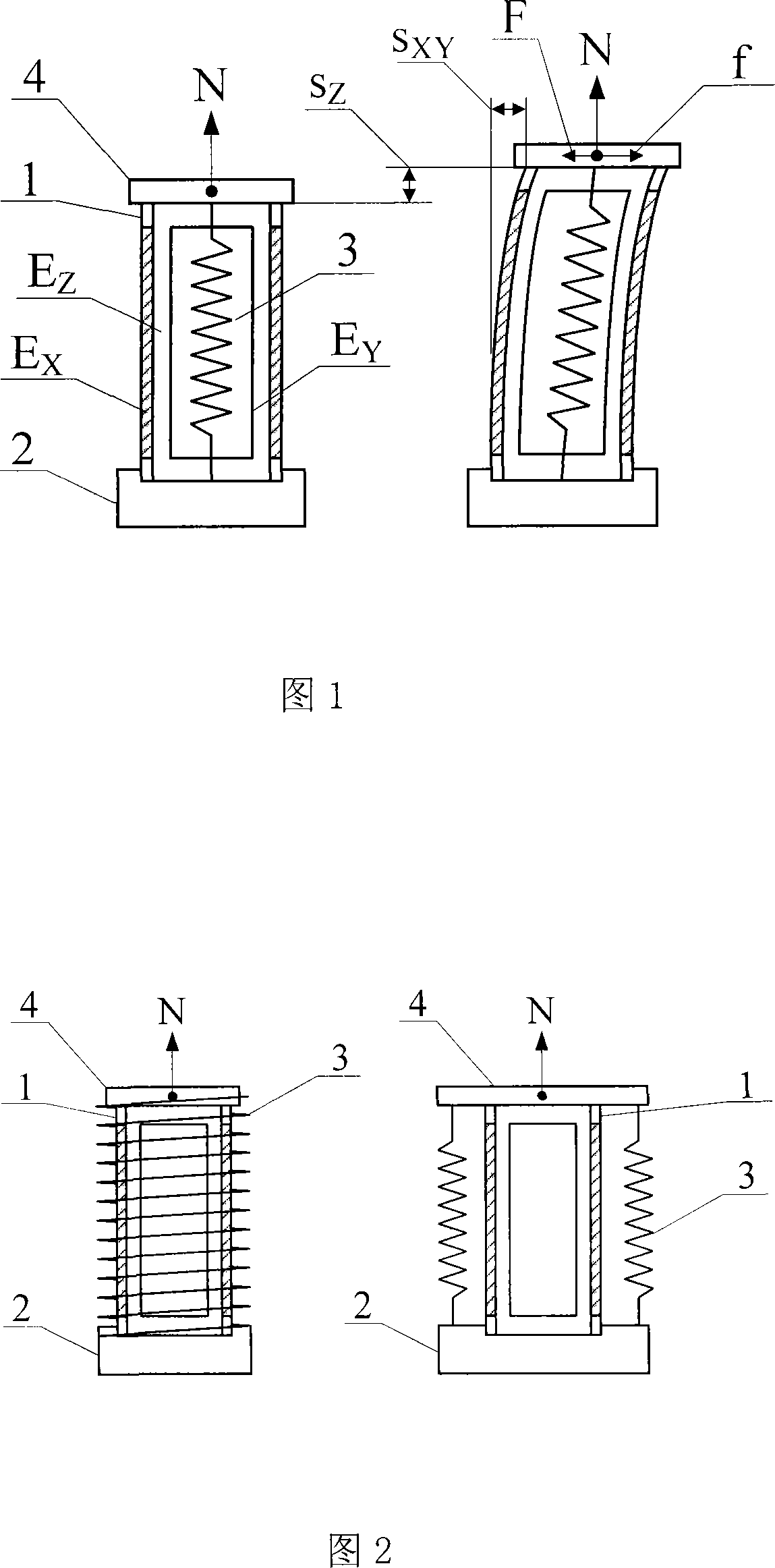
[0047] Referring to Fig. 1, one end of the XYZ piezoelectric scanning tube 1 is fixed on the base 2, the tensioner 3 pulls the pressing piece 4 to the base 2, and the scanning end of the XYZ piezoelectric scanning tube 1 supports the pressing piece 4 so that it will not be pulled Base 2. In this way, the effect of pressure N is generated between the pressing piece 4 and the scanning end of the XYZ piezoelectric scanning tube. The tensioner 3 can be a spring, a magnet, a hanging hammer, an elastic cord or a pressing piece itself. The tensioner 3 is placed inside the XYZ piezoelectric scanning tube 1 .

[0048] The frictionless inertial step scanner of this embodiment can work in the microscopic scanning and positioning mode, and can also work in the macroscopic large-scale stepping mode.

[0049] For microscopic scanning and positioning mode, the X electrode E of the XYZ piezoelectric scanning ...

Embodiment 2

[0051] Embodiment 2: Frictionless inertial step scanner with external tensioner

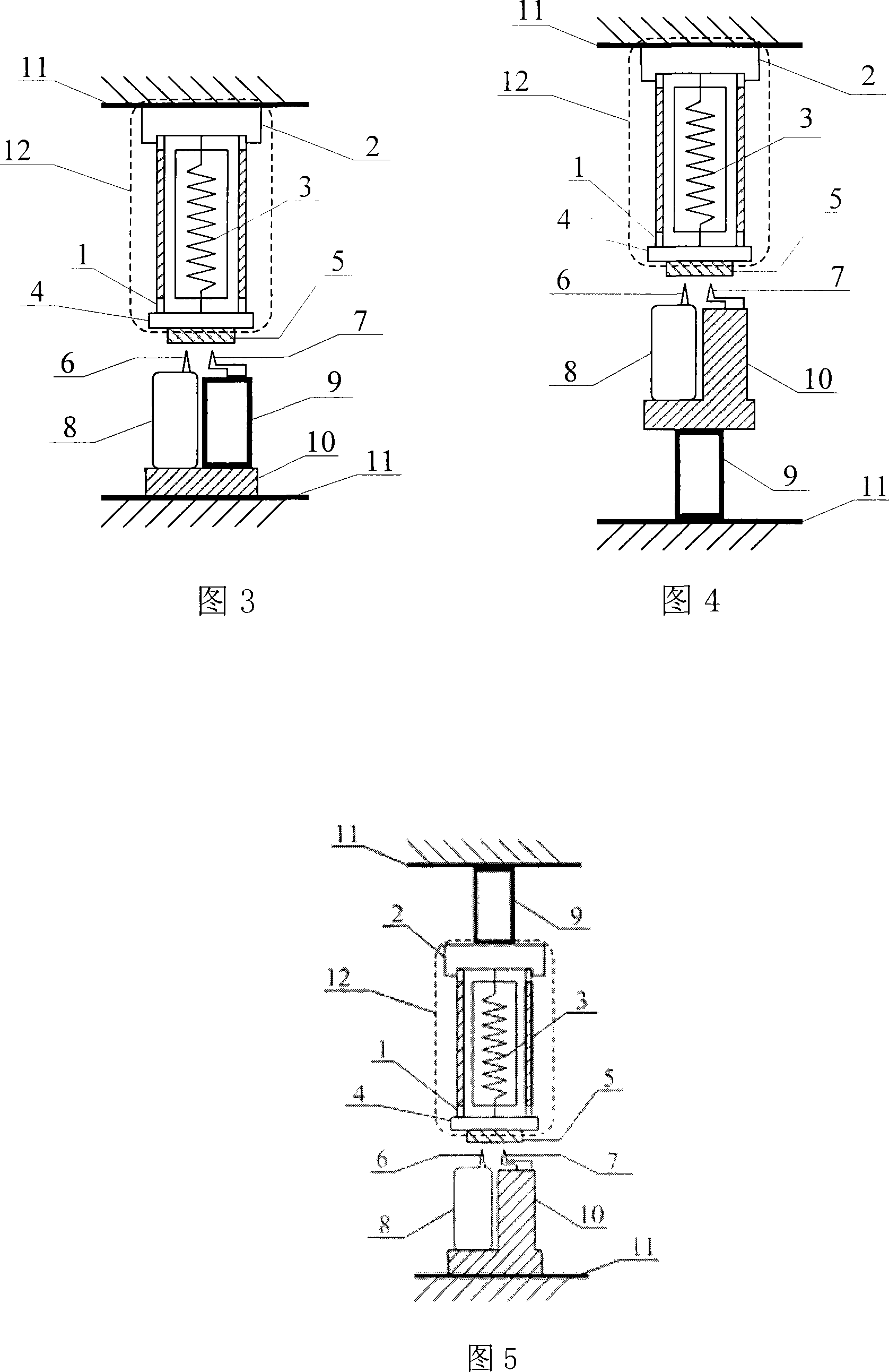
[0052] FIG. 1 shows the situation that the tensioner 3 is placed inside the XYZ piezoelectric scanning tube 1 . The position of the tensioner 3 can also be outside the XYZ piezoelectric scanning tube 1, as shown in FIG. 2 .

Embodiment 3

[0053] Example 3: Non-spring tensioner frictionless inertial step scanner

[0054] The setting of the tensioner is to pull the pressure piece to the base and interact with the scanning end of the XYZ piezoelectric scanning tube with pressure. Therefore, the tensioner can be located inside or outside the XYZ piezoelectric scanning tube, and its type can also be It is non-spring type, such as: elastic cord, magnet that attracts the pressing piece, a hanging hammer hanging under the pressing piece or the pressing piece itself (the pulling force that generates the pressure comes from the gravity of the pressing piece itself) and other devices that can generate the pressure .


PUM


Abstract

The invention relates to a frictionless inertia step scanner, which is characterized in that an expander pulls a sheet to a base, one end of a XYZ piezoelectric scanning tube is fixed on the base while another end supports the sheet and generates pressure. When in use, the invention adds a Z extension signal and a slow XY signal, quickly evacuates the two signals to process the XY evacuation in the Z retraction and use the Z-axis inertia force of the sheet to eliminate the XY-axis friction force, repeats and generates XY-axis step without friction interference. The invention has high large-scale step positioning precision and small-scale scanning and positioning functions, which leads in two independent Z-axis positioning devices to adjust the distance between two probes and sample, uses frictionless inertia step scanning device to accurately feed the test point of the first probe on the sample into the scanning range of the second probe, to realize one-point scanning dual-probe microscope, with complete, reliable and effective data.

Description

technical field [0001] The invention relates to a piezoelectric scanning stepper and a scanning probe microscope, in particular to a frictionless inertial stepping scanner and its control method, as well as the same-point scanning double-probe microscope made therefrom. Background technique [0002] The existing XYZ piezoelectric scanning tube has been widely used in the field of scanning probe microscope due to its small size, simple operation and reliability, completely eliminating the early tripod scanning structure. However, it can only scan, measure spectral data and image the sample surface in a tiny range of about 10-100 microns, because the piezoelectric material of the XYZ piezoelectric scanning tube has a very small piezoelectric coefficient for the sake. At present, the principle of piezoelectric inertial stepper can be used to move the sample step by step on the scanning tube to obtain a cumulative and large-scale movement. The specific method is: first let the...

Claims


Application Information

Patent Timeline
IPC IPC(8): G01N13/10G12B21/22G01Q10/00
Inventor 陆轻铀
Owner UNIV OF SCI & TECH OF CHINA
Why Eureka
Try Eureka