Bridge damping device

A vibration damping device and bridge technology, applied in bridges, bridge parts, bridge construction, etc., can solve the problems of single vibration damping facilities and poor vibration damping effect, and achieve the goal of ensuring vibration damping effect, simple structure, and bridge safety Effect

Active Publication Date: 2019-06-04
JIANGXI PROVINCIAL TRANSPORTATION ENG GRP
View PDF9 Cites 9 Cited by
  • Summary
  • Abstract
  • Description
  • Claims
  • Application Information

AI Technical Summary

Problems solved by technology

Although the device can reduce the vibration of the bridge, the device has a single vibration reduction facility and the vibration reduction effect is not good

Method used


Image

  • Bridge damping device
  • Bridge damping device
  • Bridge damping device

Examples


Embodiment 1

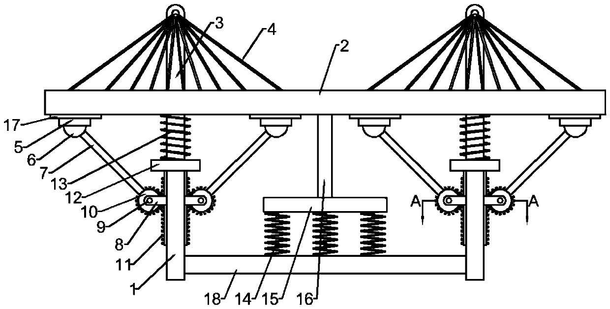
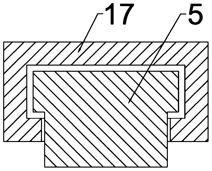
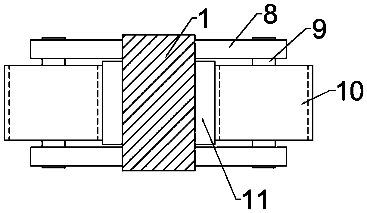
[0020] Example 1: Please refer to Figure 1-3 , a bridge damping device, comprising a plurality of supporting piers 1, the top of the supporting piers 1 is fixedly connected with a bridge deck 2, the bridge deck 2 is slidingly connected with the supporting piers 1 by bolts, and the left and right sides of the supporting piers 1 are fixedly connected There is a limit chute 17 located below the bridge deck 2, the inside of the limit chute 17 is slidably connected with a limit slider 5, and the bottom of the limit slider 5 is fixedly connected with a rotary hinge 6, and the bottom of the rotary hinge 6 is fixed. A swing connecting rod 7 is connected, the middle part of the supporting pier 1 is fixedly connected with a bearing bracket 8, the outside of the bearing bracket 8 is rotatably connected with a positioning shaft 9, and the outside of the positioning shaft 9 is fixedly connected with a driven gear 10, and the driven gear 10 is connected with the swing connecting rod 7 The ...

Embodiment 2

[0025] Embodiment 2: This embodiment is a further improvement of the previous embodiment: a support connecting bottom bar 18 is fixedly connected between the adjacent supporting piers 1, and a number of second springs 14 are fixedly connected above the supporting connecting bottom bar 18. The top of the second spring 14 is fixedly connected with a horizontal damping base plate 15, and the top of the horizontal damping base plate 15 is fixedly connected with a vibration damping support rod 16. The vibration damping support rod 16 is fixed on the bottom of the bridge deck 2. The horizontal damping bottom plate 15 is driven downward by supporting the connecting bottom bar 18 to press the second spring 14, and the second spring 14 will further dampen the vibration, improve the stability of the bridge, and ensure safety.

[0026] The fixed connection position between the vibration-damping support rod 16 and the bridge deck 2 is located in the middle of the adjacent supporting pier 1...


PUM


Abstract

The invention discloses a bridge damping device, which belongs to the field of bridges. The device comprises a plurality of supporting piers, and the tops of the supporting piers are fixedly connectedwith bridge decks; the bridge decks are in sliding connection with the supporting piers through bolts. Limiting sliding grooves located below the bridge decks are fixedly connected to the left side and the right side of the supporting piers correspondingly, limiting sliding blocks are slidably connected to the inner sides of the limiting sliding grooves correspondingly, rotating hinges are fixedly connected to the lower portions of the limiting sliding blocks, swing connecting rods are fixedly connected to the lower portions of the rotating hinges, and a bearing support is fixedly connected to the middle of each supporting pier. During use, damping is performed through the double damping devices, so that the damping effect is guaranteed; and when the vibration amplitude of the device is large, the swing connecting rods can drive gears to rotate, then first springs are compressed through transmission racks and sliding positioning blocks to conduct primary damping; meanwhile, damping supporting rods and horizontal damping bottom plates compress second springs to conduct further damping, vibration energy is thoroughly absorbed, and bridge safety is guaranteed.

Description

technical field [0001] The invention relates to the field of bridges, in particular to a bridge damping device. Background technique [0002] Bridges generally refer to structures erected on rivers, lakes and seas to allow vehicles and pedestrians to pass smoothly. In order to adapt to the modern high-speed development of the transportation industry, bridges are also extended to buildings that cross mountain streams, poor geology or meet other transportation needs to make traffic more convenient. A bridge is generally composed of a superstructure, a substructure, a support and ancillary structures. The superstructure is also called a bridge span structure, which is the main structure for crossing obstacles; the substructure includes abutments, piers and foundations; Or the force transmission device installed at the supporting place of the bridge abutment; the auxiliary structures refer to the bridge head strap, conical slope protection, revetment, diversion engineering, etc...

Claims


Application Information

Patent Timeline
Patent Type & Authority Applications(China)
IPC IPC(8): E01D19/04
Inventor 张苇
Owner JIANGXI PROVINCIAL TRANSPORTATION ENG GRP
Why Eureka
Try Eureka