Artificial lacrimal ductule

A tear duct and artificial technology, applied in eye implants, ophthalmology treatment, etc., can solve the problems of tear duct damage, failure to apply tear duct rupture, and difficult operation of the tear duct, so as to achieve the effect of reducing the difficulty of operation

Active Publication Date: 2019-06-07
PEKING UNIV THIRD HOSPITAL
View PDF3 Cites 0 Cited by
  • Summary
  • Abstract
  • Description
  • Claims
  • Application Information

AI Technical Summary

Problems solved by technology

[0004] The canaliculus fracture detection tool and the artificial lacrimal duct are two independent devices in this canaliculus repair method, and it is difficult to operate during the canaliculus repair process.
Moreover, the above-mentioned lacrimal canaliculus fracture detection tool is easy to cause damage to the uninjured canaliculus, and cannot be applied to the situation where the lacrimal canaliculi in the upper and lower eyelids are all broken

Method used


Image

  • Artificial lacrimal ductule
  • Artificial lacrimal ductule

Examples


Embodiment 1

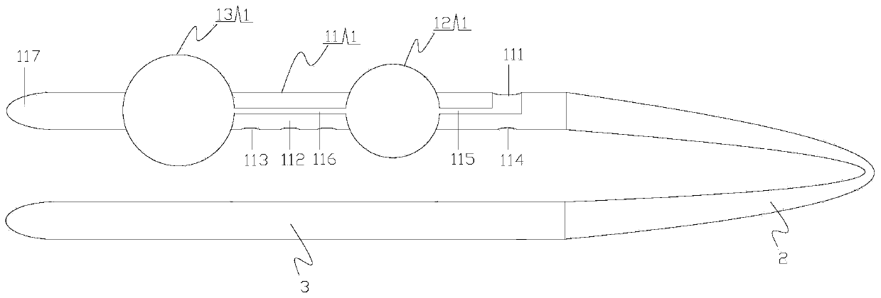
[0039] Such as figure 1 As shown, the artificial lacrimal duct of the present disclosure may include a lacrimal canaliculus fracture detection part 1 , a support part 2 and a guide part 3 connected in sequence. The lacrimal canaliculus fracture detection part 1, the support part 2 and the guide part 3 can be connected together by means of injection molding or gluing.

[0040] The lacrimal canaliculus fracture detection piece 1 includes a detection body 11 and an expansion body 12 . The detection body 11 may have a tubular structure or a rod-shaped structure or the like. The inflatable body 12 can be, for example, a balloon or a block-like structure partially provided with a flexible and stretchable membrane. As fluid enters or exits the inflatable body 12, the inflatable body 12 may expand or contract.

[0041] The detection body 11 is provided with a detection fluid inlet 111 , a detection fluid channel 112 , a detection fluid outlet 113 , an expansion fluid inlet 114 and ...

Embodiment 2

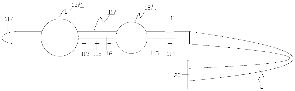
[0074] Such as figure 2 As shown, the artificial lacrimal duct of the present disclosure may include a lacrimal canaliculus fracture detection part 1 and a support part 2 connected together. The lacrimal canaliculus fracture detection part 1 and the support part 2 can be connected together by means of injection molding or gluing.

[0075] The lacrimal canaliculus fracture detection piece 1 includes a detection body 11 and an expansion body 12 . The detection body 11 may have a tubular structure or a rod-shaped structure or the like. The inflatable body 12 can be, for example, a balloon or a block-like structure partially provided with a flexible and stretchable membrane. As fluid enters or exits the inflatable body 12, the inflatable body 12 may expand or contract.

[0076] The detection body 11 is provided with a detection fluid inlet 111 , a detection fluid channel 112 , a detection fluid outlet 113 , an expansion fluid inlet 114 and an expansion fluid channel. The dete...


PUM


Abstract

The invention discloses an artificial lacrimal ductile. The artificial lacrimal ductile comprises a lacrimal ductile fracture detection part, a support part and a guide part which are sequentially connected, wherein the lacrimal ductile fracture detection part comprises a main detection body and a expansion body, a detection fluid inlet, a detection fluid channel, a detection fluid outlet, a expansion fluid inlet and an expansion fluid channel are arranged on the main detection body, and the expansion body is mounted on the main detection body; the support part is set to be used for supportinga fractured lacrimal ductile; and the guide part is set to be used for guiding one end of the support part in a lacrimal passage. The lacrimal ductile fracture detection part of the artificial lacrimal ductile disclosed by the invention can conveniently and effectively detect the fracture of the lacrimal ductile. Besides, two ends of the support part can beguided in the lacrimal passage by the lacrimal ductile fracture detection part and the guide part respectively, so that the support part supports the fractured lacrimal ductile, and the operation difficulty in implanting the artificial lacrimal ductile is effectively reduced.

Description

technical field [0001] The invention relates to the field of lacrimal canaliculus repair, in particular to an artificial lacrimal duct. Background technique [0002] The canaliculus is part of the tear duct. Tears in the human body are produced from the lacrimal gland, lubricated by the surface of the eyeball, and enter the upper and lower lacrimal canaliculi respectively located on the upper and lower eyelids respectively from the upper and lower lacrimal canaliculi on the upper and lower eyelids respectively, and then flow sequentially. Through the common lacrimal duct, lacrimal sac and nasolacrimal duct, it is discharged from the human body from the opening of the nasolacrimal duct. The opening of the above-mentioned nasolacrimal duct refers to the mouth where the lacrimal duct is located on the inferior nasal meatus. Occasionally rupture of the lacrimal duct occurs due to conditions such as eye trauma. [0003] Broken canaliculi can be repaired by implanting artificia...

Claims


Application Information

Patent Timeline
Patent Type & Authority Applications(China)
IPC IPC(8): A61F9/00A61F2/14
Inventor 周吉超张纯李涛魏滨田彦杰周辰瑜
Owner PEKING UNIV THIRD HOSPITAL
Why Eureka
Try Eureka