Information providing method, device and system

A technology of correlated information and information conversion, applied in stereo systems, closed-circuit television systems, optical observation devices, etc., can solve problems such as single function, and achieve the effect of increasing functions

Active Publication Date: 2019-06-07
BEIJING 7INVENSUN TECH
25 Cites 4 Cited by

AI-Extracted Technical Summary

Problems solved by technology

[0003] At present, the function of vehic...

Method used

In summary, in the information providing method provided by the embodiment of the present application, the driving environment image is obtained; the first gaze information for the user is obtained; the first gaze information of the user is converted into the second gaze information of the user based on preset rules ; Determine the target object based on the user's second gaze information, the target object is the object that the user pays attention to in the corresponding position in the driving environment image; at least some areas of the control control provide the associated information of the target object,...

Abstract

The embodiment of the invention provides an information providing method, device and system. The information providing method comprises the steps that driving environment images are obtained; first gazing information of a user is obtained; the first gazing information of the user is converted to second gazing information of the user based on a preset rule; a target object is determined based on the second gazing information of the user, and the target object is the object at the corresponding position in the driving environment images concerned by the user; and at least part of the area of a control part is controlled to provide associated information of the target object. By utilizing the information providing method, the user can obtain the associated information of the object concernedby the user at the at least part of the area of the control part, the function of vehicle-mounted control equipment is increased, and thus the function of the vehicle-mounted control equipment is notsimplex.

Application Domain

Closed circuit television systemsSteroscopic systems +1

Technology Topic

Computer visionControl equipment +2

Image

  • Information providing method, device and system
  • Information providing method, device and system
  • Information providing method, device and system

Examples

  • Experimental program(1)

Example Embodiment

[0034] The technical solutions in the embodiments of the present invention will be clearly and completely described below in conjunction with the accompanying drawings in the embodiments of the present invention. Obviously, the described embodiments are only a part of the embodiments of the present invention, rather than all the embodiments. Based on the embodiments of the present invention, all other embodiments obtained by those of ordinary skill in the art without creative work shall fall within the protection scope of the present invention.
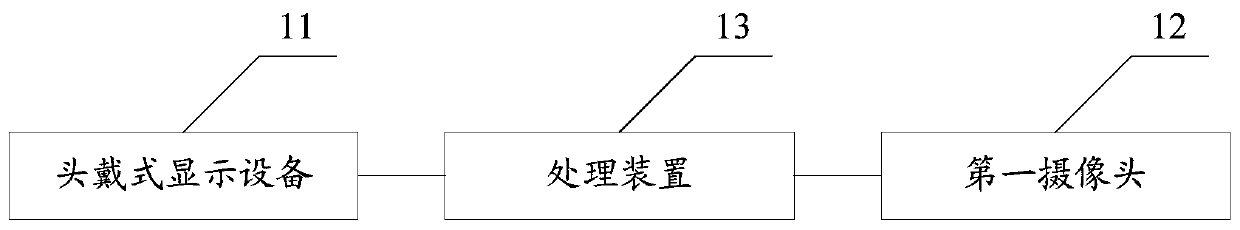
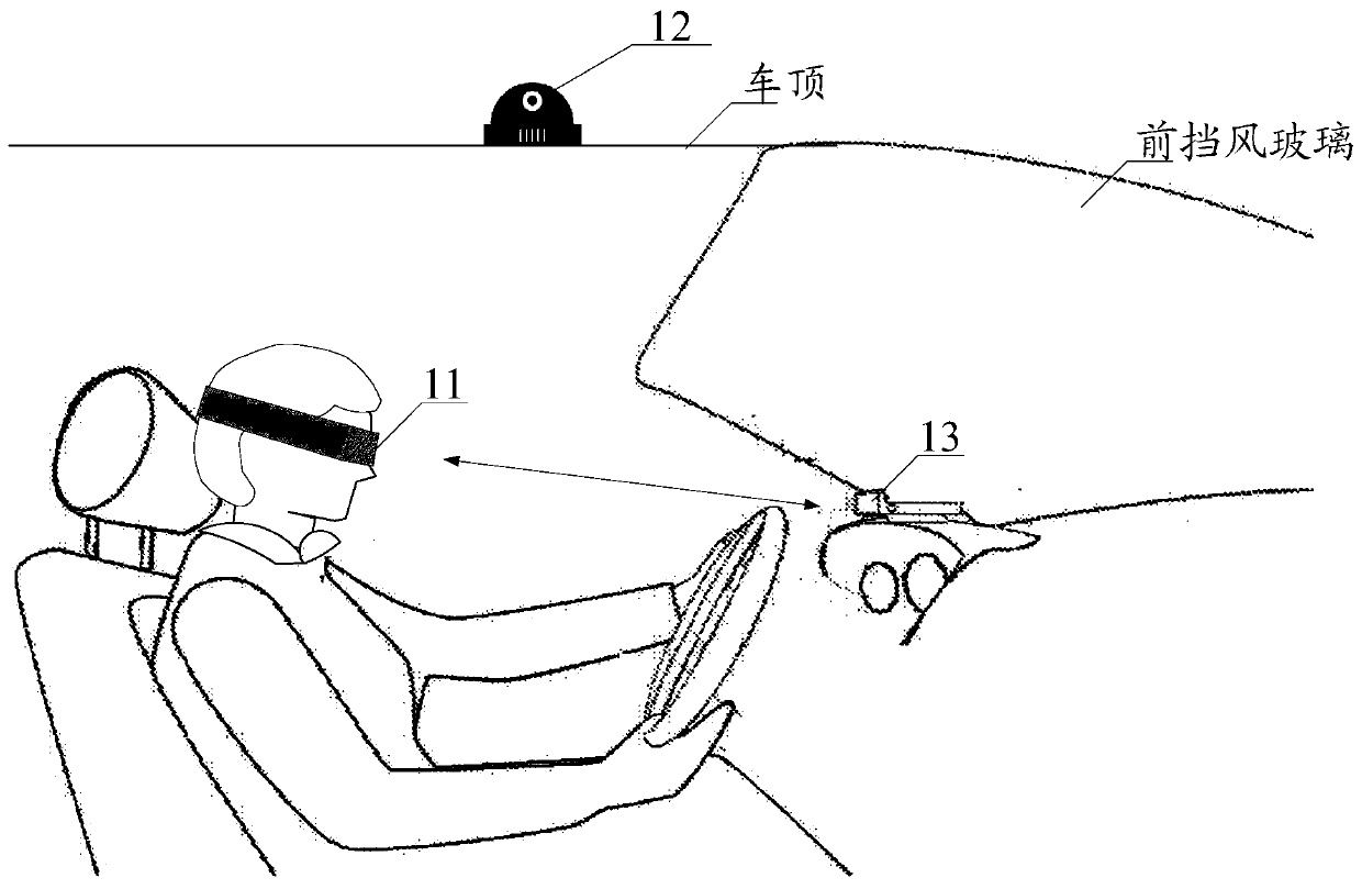
[0035] With the development of vehicle intelligence, more and more on-board control devices, for example, HUD (Head Up Display), HUD is used to project important driving information such as multi-function dashboard or navigation to the front windshield of the vehicle On the glass, the driver can see important driving information such as speed or navigation without bowing his head or turning his head.
[0036] At present, on-board control devices can only display driving information such as multi-function dashboards or navigation, such as HUD. The current on-board control devices have a single function. For example, the current on-board control devices cannot display the real driving environment.
[0037] In view of this, the embodiment of the present application provides an information providing method to increase the functions of the on-board control device, so that the function of the on-board control device is not single. The information providing method can be applied to an information providing system, such as figure 1 As shown, this is a structural diagram of an implementation manner of the information providing system provided in this embodiment of the application, and the information providing system includes:
[0038] The head-mounted display device 11, the first camera 12 and the processing device 13, wherein:
[0039] The first camera 12 is used to obtain driving environment images.
[0040] Optionally, the first camera may collect the surrounding driving environment of the vehicle to obtain an image of the driving environment.
[0041] In an optional embodiment, the first camera 12 may be a 360° panoramic camera; or, the first camera 12 may include a plurality of cameras located in different positions of the vehicle, so that the first camera 12 can collect information about the location of the vehicle. Surrounding driving environment.
[0042] In an optional embodiment, the first camera 12 may include one or more 3D cameras, and the 3D cameras may collect the distances of objects contained in the surrounding driving environment relative to the vehicle to obtain a three-dimensional image of the driving environment. It can be called a three-dimensional driving environment image as a deep driving environment image.
[0043] In an optional embodiment, the driving environment image may be a two-dimensional image.
[0044] The head-mounted display device 11 is used to obtain the first gaze information of the user, and the first gaze information of the user is the gaze information determined by the user in the first coordinate system.
[0045] In an optional embodiment, the head-mounted display device 11 includes an eye-controlled tracking device;
[0046] The eye control tracking device includes at least one second camera, and the at least one second camera is used to obtain the user's first gaze information.
[0047] In an optional embodiment, the eye tracking device may include at least one infrared light source, and the at least one infrared light source is used to project infrared light onto at least the eye area of ​​the user. Correspondingly, the at least one second camera is used to obtain the eye image of the user when the infrared light is projected under at least the eye area of ​​the user to obtain the user's first gaze information.
[0048] The characteristics of the human eye under the action of infrared light can be used to improve the accuracy of obtaining the user's eye image. Because the user's pupils reflect more light under the irradiation of infrared light.
[0049] In an optional embodiment, the at least one second camera includes one or more 3D cameras, and/or, one or more 2D cameras.
[0050] Optionally, the 3D camera may acquire the user's eye image that characterizes the relative position between the user's eyes and the eye tracking device 31.
[0051] The processing device 13 is configured to convert the first gaze information of the user into the second gaze information of the user based on a preset rule; determine a target object based on the second gaze information of the user, and the target object is the user's attention to the An object at a corresponding position in the driving environment image; at least a part of the control control provides associated information of the target object, wherein providing the associated information of the target object includes playing or displaying the associated information of the target object.
[0052] In an optional embodiment, the processing device 13 belongs to the head-mounted display device 11, and in another optional embodiment, the processing device 13 and the head-mounted display device 11 are independent of each other.
[0053] In an optional embodiment, the control may belong to the head-mounted display device 11. For example, the control may be a display in the head-mounted display device 11; in another optional embodiment, the control is independent of the head-mounted display device. 11, for example, at least a partial area of ​​the front windshield.
[0054] In summary, since at least a part of the control area provides the associated information of the target object, the function of the vehicle control device is increased, and the function of the vehicle control device is not single.
[0055] Wherein, providing the associated information of the target object includes playing or displaying the associated information of the target object.
[0056] For a more vivid explanation figure 1 The information provision system shown, such as figure 2 As shown, the examples provided for this application and figure 1 A specific example diagram of the corresponding information provision system.
[0057] figure 2 The installation positions of the first camera 12 and the processing device 13 in the vehicle are only for illustration, and the embodiment of the present application does not limit the installation positions of the first camera 12 and the processing device 13 in the vehicle.
[0058] figure 2 The first camera 12 is located on the roof of the vehicle. The embodiment of the application does not limit the position of the first camera 12 in the vehicle. For example, the first camera 12 may also be located in the lights of the left door, and/or the right door The lights, and/or, any position of the trunk shell, etc.
[0059] In an alternative embodiment, the processing device 13 may be located figure 2 The position shown is under the front windshield; the embodiment of the present application does not limit this, and the processing device 13 can be located at any other position in the vehicle.
[0060] From figure 2 It can be seen that the user can carry the head-mounted display device 11. The first camera 12 and the head-mounted display device 11 can interact with the processing device 13 respectively, so that the user can see the associated information of the target object the user is paying attention to through the display area.
[0061] Such as image 3 As shown, this is a structural diagram of another implementation of the information providing system provided in this embodiment of the application, and the information providing system includes:
[0062] The first camera 12, the eye tracking device 31, the processing device 32 and the display area (not shown in the figure), wherein:
[0063] The function of the first camera 12 and figure 1 The functions of the first camera 12 shown are the same, and will not be described here.
[0064] The eye control tracking device 31 is configured to obtain the user's first gaze information, where the user's first gaze information is the gaze information determined by the user in a first coordinate system.
[0065] In an optional embodiment, the eye tracking device 13 includes at least one second camera, and the at least one second camera is used to obtain the user's first gaze information.
[0066] In an optional embodiment, the eye tracking device may include at least one infrared light source, and the at least one infrared light source is used to project infrared light onto at least the eye area of ​​the user. Correspondingly, the at least one second camera is used to obtain the eye image of the user when the infrared light is projected under at least the eye area of ​​the user to obtain the user's first gaze information.
[0067] The characteristics of the human eye under the action of infrared light can be used to improve the accuracy of obtaining the user's eye image. Because the user's pupils emit more light under the irradiation of infrared light.
[0068] In an optional embodiment, the at least one second camera includes one or more 3D cameras, and/or, one or more 2D cameras.
[0069] Optionally, the 3D camera may acquire the user's eye image that characterizes the relative position between the user's eyes and the eye tracking device 31.
[0070] In an alternative embodiment, the display area may be at least a partial area of ​​the front windshield.
[0071] The processing device 32 is configured to convert the first gaze information of the user into the second gaze information of the user based on a preset rule, and determine a target object based on the second gaze information of the user, and the target object is the user's attention to the driving An object at a corresponding position in the environment image; at least a part of the control control provides associated information of the target object.
[0072] Wherein, providing the associated information of the target object includes playing or displaying the associated information of the target object.
[0073] In summary, since the control can provide the associated information of the target object that the user is currently paying attention to, the functions of the on-board control device are increased, so that the function of the on-board control device is not single.
[0074] For a more vivid explanation image 3 The information provision system shown, such as Figure 4 As shown, the examples provided for this application and image 3 A specific example diagram of the corresponding information provision system.
[0075] image 3 The installation positions of the eye-controlled tracking device 31 and the processing device 32 in the vehicle are only for illustration, and the embodiment of the present application does not limit the installation positions of the eye-controlled tracking device 31 and the processing device 32 in the vehicle.
[0076] image 3 The eye control tracking device 31 and the processing device 32 shown in the figure are independent devices. Optionally, the eye control tracking device 31 and the processing device 32 can be integrated together as one device.
[0077] In an optional embodiment, the control is at least a partial area of ​​the front windshield, image 3 The middle processing device 32 may project the associated information of the target object on the front windshield; or, the control is a display, that is, the front windshield contains at least a display, and the reflected light of the light corresponding to the information provided by the control can be projected to the user’s Eyes, for example, image 3 The dotted line shown in the figure is the path of the light projected to the front windshield and the path of the reflected light transmitted to the user's eyes, so that the user can see the associated information of the target object.
[0078] In an alternative embodiment, figure 1 with image 3 The control in the information providing system shown can be a vehicle-mounted multimedia player control, which can play the stereoscopic view or related introduction associated with the target object; or, if the user is not convenient to watch while driving, he can control the vehicle-mounted multimedia player control to play the target object. Voice prompts with rhythm, melody or harmony. In an alternative embodiment, figure 1 with image 3 The control in the information providing system shown can be a display screen, and the control can display associated information of the target object.
[0079] Combine Figure 1 to Figure 4 , The following describes the information providing method provided by the embodiments of this application, such as Figure 5 As shown, the flow chart of an implementation manner of the information providing method provided by the embodiment of this application, the method includes:
[0080] Step S501: Acquire a driving environment image.
[0081] Optional, you can use figure 1 or image 3 The first camera 12 in collects driving environment images.
[0082] In an optional embodiment, the driving environment image may be a panoramic image; in another optional embodiment, the driving environment image is not a panoramic image.
[0083] In an optional embodiment, the driving environment image only includes images within the vision range of the user; in another optional embodiment, the driving environment image includes images within the vision range of the user and images that cannot be observed by the user. The image that the user cannot observe may be, for example, an image in the direction of the back of the user's head.
[0084] Step S502: Acquire first gaze information of the user, where the first gaze information of the user is the gaze information determined by the user in the first coordinate system.
[0085] Optionally, the specific means for detecting the first gaze information of the user is not limited here. For example, the first gaze information can be determined by capacitance, electromyography, Micro-Electro-Mechanical System (MEMS), gaze tracking device (such as eye tracker), or image. The image here refers to a user image acquired by an image acquisition device, and the user image can be understood as an image containing the user's eyes. The image acquisition device can acquire the user's face image, full body image, or eye image as the user image.
[0086] Optional, you can use figure 1 Head-mounted display device 11 or image 3 The middle eye tracking device 31 acquires a user image including an image of the user's eye.
[0087] Step S501 and step S502 can be executed at the same time, or, step S501 is executed before step S502, or, step S502 is limited to step S501.
[0088] In an optional embodiment, step S502 may include before step S502: step one, acquiring user eye images; step two, acquiring user eye feature information based on the user eye image; step three, based on the user eye image The feature information determines the first gaze information of the user in the first coordinate system. Determine eye feature information according to the user's eye image, the eye feature information including: pupil position, pupil shape, iris position, iris shape, eyelid position, eye corner position, spot (also called Purkin spot) position, etc. One or more of them. The first gaze information of the user may include one or more of gaze vector, gaze point coordinates, and gaze depth.
[0089] Optionally, the gaze vector includes: the user's line of sight direction parameter and the user's pupil coordinates; optionally, the user's pupil coordinates include one or more of the center point coordinates of the user's two pupils and the coordinates of the user's two pupils.
[0090] Optionally, the gaze point coordinates include: coordinates of a gaze position area where the user gazes at the driving environment.
[0091] Optionally, the gaze point coordinates include the coordinates of one or more points, and multiple points may form an area.
[0092] Optionally, the depth of the gaze point includes: the user's line of sight direction parameter, and the user's line of sight depth.
[0093] Optionally, if the driving environment image is a three-dimensional image, the user's line of sight depth refers to the length from the user's eyes to the user's gaze at the corresponding position in the driving environment image.
[0094] The following describes the method for acquiring the user's line of sight direction parameter. The embodiments of the present application provide but are not limited to the following methods.
[0095] In the first method, the eye tracking method can be used to obtain the user's line of sight direction parameter. The specific method includes: performing image analysis on the user's eye image collected by at least one second camera, and calculating the coordinates of the center point of the user's pupils. Then use the line of sight estimation algorithm to calculate the user's line of sight direction parameters according to the coordinates of the center point of the pupils of the eyes.
[0096] In the second method, the information providing system may include a near infrared sensor NIR Sensor. Optionally, the near infrared sensor NIR Sensor may be located on the head-mounted display device 11; optionally, the near infrared sensor NIR Sensor and the head-mounted display device 11 Independent.
[0097] The infrared light emitted by the near-infrared sensor NIR Sensor will illuminate the user's eyes. At this time, the iris of the eye will reflect the infrared light. The reflected light can be detected by the near-infrared sensor to determine the sight direction parameters of the user's eyeball.
[0098] Step S503: Convert the first gaze information of the user into second gaze information of the user based on a preset rule, where the second gaze information is the gaze information determined by the user in a second coordinate system.
[0099] In an optional embodiment, the step of converting the first gaze information of the user in the first coordinate system into the second gaze information of the user in the second coordinate system based on a preset rule may include:
[0100] Convert the first gaze information located in the first coordinate system into second gaze information located in the second coordinate system based on a preset conversion rule; based on the second gaze information located in the second coordinate system To obtain the location area where the user is gazing at the driving environment image.
[0101] There are many ways to realize the conversion of the first gaze information in the first coordinate system into the second gaze information in the second coordinate system. The embodiments of the present application provide but are not limited to the following methods.
[0102] The first type: determine the first gaze information in the first coordinate system; determine the coordinates corresponding to the objects contained in the driving environment image in the second coordinate system; based on the first object in the first coordinate system and the second in the second coordinate system The preset fixed relative position between the objects converts the first gaze information in the first coordinate system into the second gaze information in the second coordinate system.
[0103] The aforementioned preset conversion rule includes: based on the preset fixed relative position between the first object and the second object, and the difference between the coordinates of the first object in the first coordinate system and the coordinates of the first object in the second coordinate system relationship.
[0104] Optionally, the first coordinate system may be a coordinate system established by the location of the first object as the coordinate origin. The second coordinate system may be a coordinate system established by the location of the second object as the coordinate origin.
[0105] Optionally, the first object is an eye tracking device, and the second object is a first camera.
[0106] The second type: determine the first gaze information in the first coordinate system. Determine the respective coordinate positions of the objects contained in the driving environment image in the third coordinate system. Based on the preset fixed position of the first object in the first coordinate system, the preset fixed position of the second object in the third coordinate system, and the preset fixed positions of the first object and the second object in the second coordinate system, respectively, Determine the coordinate position of the object included in the driving environment image in the second coordinate system, and the second gaze information in the second coordinate system.
[0107] Optionally, the second coordinate system is a coordinate system different from the first coordinate system and the third coordinate system. Optionally, the second coordinate system is a GPS coordinate system.
[0108] Among them, the GPS coordinate system is a real-world coordinate system, and is a coordinate system used to determine the position of a feature on the earth.
[0109] Optionally, in the above two implementation manners, the position of the first object in the first coordinate system is fixed, and the position of the second object in the third coordinate system is fixed; or, the second The position of the object in the third coordinate system is fixed, and the position of the first object in the first coordinate system changes within a preset range.
[0110] Optional, in image 3 or Figure 4 In the application scenario shown, the third coordinate system is a coordinate system established by one or more points (such as the first camera 12) that are fixed relative to the vehicle position. The first coordinate system may be a coordinate system established with respect to a point (for example, an eye-control tracking device) that is fixed relative to the vehicle position.
[0111] From image 3 or Figure 4 It can be seen that after the first camera 12 and the eye tracking device 31 are installed, the positions are fixed. If the second object is the first camera 12 and the first object is the eye tracking device 31, then the first object is The relative position between the second objects is fixed, so the above is called a preset fixed position.
[0112] If the position of the first object in the first coordinate system changes within the preset range, it will not affect the subsequent determination of the target object from the driving environment image, which will be described below.
[0113] Optional, in figure 1 or figure 2 In the application scenario shown, the third coordinate system is a coordinate system established with a fixed point relative to the vehicle position (for example, the first camera 12) as the origin. The first coordinate system may be a coordinate system established by a point (for example, the eye tracking device 31) that changes within a preset range relative to the vehicle position as the origin.
[0114] Understandably, the user is carrying figure 2 During the process of the head-mounted display device shown, the user's head will move, for example, sitting or looking right or looking forward or looking back or looking down, etc., when the user's head moves During the process, the head-mounted display device will also move accordingly (if the eye tracking device 31 is located in the head-mounted display device), so that the eye tracking device 31 on the head-mounted display device will also be displayed with the head-mounted display device. The device moves while moving, that is, the position of the first object in the first coordinate system is within a preset range.
[0115] It is understandable that the user’s head movement range is not large in order to ensure safety during driving; that is, figure 1 or figure 2 The eye-controlled tracking device 31 in the head-mounted display device shown moves within a preset range, and the location area of ​​the driving environment image that the user pays attention to is not changed. For a better understanding of those skilled in the art, a specific example is given below for description.
[0116] Such as Image 6 As shown, a schematic diagram of a coordinate system conversion provided by an embodiment of this application.
[0117] Image 6 Including: the third coordinate system 61, the first coordinate system 62, and the conversion coordinate system 63; optionally, the position coordinates corresponding to the objects contained in the driving environment image in the conversion coordinate system 63 need to be obtained, and, in the conversion coordinate system Gaze information under 63.
[0118] Optionally, the conversion coordinate system 63 may be the first coordinate system or the second coordinate system or the third coordinate system.
[0119] Assuming that the driving environment image includes: Object 1, Object 2, and Object 3. The coordinates of the three objects contained in the driving environment image in the third coordinate system are as follows: Image 6 Shown.
[0120] Optionally, the origin O of the third coordinate system 61 may be the location of the first camera 12; if the first camera 12 includes multiple cameras, the origin O of the third coordinate system may be the location of any camera.
[0121] In the first coordinate system 62, the first gaze information is represented by a dash-dotted line (it is assumed that the eye feature information includes a gaze vector and/or a gaze depth).
[0122] Still with Image 6 As an example, suppose that the origin position of the third coordinate system 61 is the position of the first camera 12, the origin position of the first coordinate system 62 is the position of the eye tracking device 31, the first object is the first camera 12, and the second object Is the eye tracking device 31, then Image 6 The dotted line between the origin of the third coordinate system 61 and the first coordinate system 62 indicates the preset fixed relative position between the first camera 12 and the eye tracking device 31.
[0123] Since the preset fixed relative position is fixed, the transformed coordinates in the transformed coordinate system are very accurate.
[0124] To figure 1 or figure 2 Take the scene shown as an example. Assume that the double-dotted line arrow in the converted coordinate system 63 represents real gaze information, and the single-dotted line arrow represents a preset fixed position based on a small range change between the eye tracking device 31 and the first camera 12 The gaze information obtained from Image 6 It can be seen that the double-dot-dash arrow and the single-dot-dash arrow both point to the same object, such as Image 6 Object shown 2.
[0125] In summary, no matter which of the above two methods is used, the coordinate position of the object contained in the driving environment image in the first coordinate system is transformed with the coordinate position of the gaze information in the third coordinate system to obtain the same coordinate. The coordinate position and gaze information of the object contained in the driving environment image under the system.
[0126] S504: Determine a target object based on the second gaze information of the user, where the target object is an object that the user pays attention to at a corresponding position in the driving environment image.
[0127] The target object may include one or more objects.
[0128] Optionally, the objects in the driving environment image may include: people, and/or, animals, and/or, houses, and/or, shopping malls, and/or, newsstands, and/or, vehicles, and/or, Trees, and/or roads, and/or road signs, and/or road speed limit signs, and/or road violation shooting devices, etc.
[0129] Optional, you can use figure 1 or image 3 The shown processing device determines the target object based on the user's second gaze information. Optional, figure 1 or image 3 The processing device shown can also detect and recognize objects contained in the driving environment image. Optional, figure 1 or image 3 The shown processing device can use the object recognition model to detect and recognize the objects contained in the driving environment image.
[0130] Optionally, the object recognition model is obtained through neural network training. The input of the object recognition model is the image to be tested (for example, driving environment image), and the output can include any of the following: the image to be tested does not include any objects, or the category of the object contained in the image to be tested, or the image to be tested contains The category of the object and the location area of ​​the contained object in the image to be measured.
[0131] The image to be tested can include objects of multiple categories, and the object recognition model can output the category of each object contained in the image to be tested.
[0132] The category of an object can be: people, or, animals, or, houses, or, shopping malls, or, newsstands, or, vehicles, or, trees, or, roads, or, road signs, or, road speed limit signs , Or, road illegal shooting device, etc.
[0133] In an optional embodiment, determining the target object based on the second gaze information of the user includes:
[0134] Based on the second gaze information of the user, acquiring the location area where the user is gazing at the driving environment image; acquiring the target object included in the location area in the driving environment image.
[0135] It is mentioned in step S502 that the first gaze information may include one or more of gaze vector, gaze point coordinates, and gaze depth.
[0136] In an optional embodiment, the first gaze information represents a gaze vector, and the gaze vector in the first coordinate system is converted into the gaze vector in the second coordinate system. In the second coordinate system, the gaze vector can be obtained based on the gaze vector. The pupil coordinates are the starting position, and a straight line is drawn along the line of sight represented by the user's line of sight parameter. The intersection of the line and the driving environment image corresponds to the location area where the user pays attention to the driving environment image. The location area includes the intersection.
[0137] In an optional embodiment, if the first gaze information represents the gaze point coordinates, the gaze point coordinates in the first coordinate system are converted into the gaze point coordinates in the second coordinate system. In the second coordinate system, the gaze point coordinates may be based on the gaze point. Point coordinates to obtain the location area in the image of the driving environment that the user pays attention to. Optionally, the location area includes fixation point coordinates.
[0138] In an optional embodiment, if the first gaze information indicates the gaze depth, the gaze depth in the first coordinate system is converted into the gaze depth in the second coordinate system. In the second coordinate system, if the driving environment The image is a three-dimensional image. Then there are one or more points where the driving environment image intersects the straight line that characterizes the user's line of sight. For example, there is building B behind building A. Then, based only on the direction of the user's line of sight, the user's gaze can be determined It is the direction of Building A, but it is not certain whether the user is looking at Building A or Building B.
[0139] Optionally, a vector with a direction can be used to indicate the depth of the gaze point. If the intersection of the vector and the driving environment image is at the position of Building A, then the user is looking at Building A, and if the intersection of the vector and the driving environment image is at B The location of the building, then the user is looking at the B building.
[0140] In an optional embodiment, the location area where the user is gazing at the driving environment image may be determined based on one or more of a gaze vector, a gaze point coordinate, and a gaze point depth.
[0141] Step S505: Control at least part of the area of ​​the control to provide the associated information of the target object, where providing the associated information of the target object includes playing or displaying the associated information of the target object.
[0142] In an optional embodiment, the partial area includes a fourth area where the user is located in the driving environment, and the fourth area can play corresponding description data and/or multimedia data of the target object.
[0143] Optionally, the control is a vehicle-mounted multimedia player control, and the relevant information of the target object may be loaded in the vehicle-mounted multimedia player control in a pre-stored database. The relevant information may be description data and/or multimedia data of the target object.
[0144] Optionally, play the three-dimensional landscape or related introduction associated with the target object in the on-board multimedia player control; optionally, if the user is not convenient to watch while driving, control the on-board multimedia player control to play the rhythm and melody associated with the target object Or the vocal reminder of the harmony.
[0145] In an optional embodiment, the control is a display screen, and the control can display associated information of the target object.
[0146] The associated information is information that does not exist in the driving environment, that is, not information in the real environment, but virtual information, that is, the embodiment of the present application uses augmented reality technology.
[0147] The associated information is information used to describe the target object. For example, if the target object is a store, the associated information can be items that are on sale in the store, or the types of goods contained in the store; if the target object is a newsstand, then The related information can be the type of newspapers and periodicals included in the newsstand; if the target object is a driving car, the related information can be the relative movement trend information of the car relative to the vehicle; if the target object is a road violation shooting device, the related information can be The distance between the road violation camera and the vehicle, and the type of road violation camera captured by the road violation camera.
[0148] Optionally, the relative movement trend information includes relative movement speed, and/or information about whether a collision will occur, and/or relative position information, so that the driver can make a judgment, thereby avoiding traffic accidents.
[0149] Such as Image 6 As shown, assuming that object 2 is a gas station, at least part of the display area can provide "Sinopec Gas Station; 92# 7.8 yuan/L; Friday’s discounted price 7 yuan/L; current vehicle remaining fuel volume 20L; based on the past "Experience can be maintained until Friday and refueling" and other related information.
[0150] Optionally, the display area mentioned in the embodiment of this application may be figure 1 or figure 2 The display area in the head-mounted display device shown; or, the display area can be Figure 4 Part or all of the front windshield shown.
[0151] In summary, in the information providing method provided by the embodiments of the present application, the driving environment image is obtained; the first gaze information for the user is obtained; the first gaze information of the user is converted into the second gaze information of the user based on the user The second gaze information determines the target object. The target object is the object at the corresponding position in the driving environment image that the user pays attention to; at least part of the area of ​​the control control provides associated information of the target object, and providing the associated information of the target object includes playing or displaying Describe the associated information of the target object. Utilizing the information providing method provided by the embodiments of the present application can enable the user to obtain the associated information of the object of interest in at least a part of the control area, increase the function of the vehicle control device, and make the function of the vehicle control device not single.
[0152] To sum up, since at least a partial area of ​​the control can provide related information about the target object that the user is currently paying attention to, the user can obtain the related information and make a corresponding decision. For example, if the user wants to buy a financial newspaper, if he sees a newsstand , But the associated information corresponding to the newsstand indicates that the newsstand only sells comics, so the user does not need to park. If there is no associated information, the user still needs to stop and ask. This application avoids the time-consuming parking and inquiry; if the user wants to To change lanes to the left, the user sees the vehicle behind the left through the rearview mirror, but the associated information of the vehicle indicates that the vehicle is accelerating and the relative distance to the own vehicle is small, the user can give up changing lanes to avoid The occurrence of traffic accidents.
[0153] It is understandable that when the user is driving the vehicle, as the vehicle moves, the driving environment where the vehicle is located is constantly changing, and the surrounding driving environment is different at different times during the movement of the vehicle. Optionally, the driving environment image includes multiple frames of driving environment sub-images. Optionally, the multiple frames of driving environment sub-images are multiple frames of continuous driving environment sub-images or multiple frames of discontinuous driving environment sub-images.
[0154] Such as Figure 7 As shown, the flow chart of an implementation manner of the information providing method provided by the embodiment of this application, the method includes:
[0155] Step S701: Acquire at least two frames of driving environment sub-images.
[0156] The driving environment image mentioned in step S501 includes one or more frames of driving environment sub-images. In the multi-frame continuous driving environment sub-images, adjacent driving environment sub-images may contain the same object, but the position and/or occupation range of the same object in different driving environment sub-images are different.
[0157] Optional, such as Figure 8a to 8d As shown, this is a schematic diagram of an application scenario in which the driving environment of a vehicle changes during a moving process provided by an embodiment of the application.
[0158] Figure 8a to Figure 8d Shows four driving environment sub-images corresponding to different times. Assuming that the vehicle 81 is a vehicle installed with the information providing system provided by the embodiment of the present application, Figure 8a to Figure 8d A group of children running, adults standing still, moving vehicles, gas stations, and roads are objects included in the sub-image of the driving environment of the vehicle 81. From Figure 8a to Figure 8d It can be seen that the driving environment of the vehicle changes during the continuous driving of the vehicle.
[0159] Changes in the driving environment include but are not limited to the following changes: the relative position of the same object contained in the driving environment and the vehicle 81 changes (for example, Figure 8a to Figure 8d The relative position of a group of children and the vehicle 81 changes), and/or the relative speed changes, etc.
[0160] The driving environment changes during the movement of the vehicle, and the sub-images of different driving environments are different.
[0161] Different driving environment sub-images include, but are not limited to, the following differences: the same object contained in different driving environment sub-images has different positions (for example, Figure 8a to Figure 8d In a group of children in different positions), and/or, the same object contained in different driving environment sub-images occupy different ranges (for example, Figure 8a to Figure 8d The range occupied by the middle car is different), and/or, different driving environment sub-images contain different objects.
[0162] Step S702: Obtain the first gaze information of the user for the sub-image of the driving environment at each moment; convert the first gaze information of the user into the second gaze information of the user based on a preset rule; determine the gaze information based on the second gaze information of the user The object that the user pays attention to in the sub-image of the driving environment.
[0163] Step S703: Determine at least part of the same objects in the objects corresponding to the multiple frames of driving environment sub-images as the target objects.
[0164] Step S704: Control at least part of the display area to display the associated information of the target object.
[0165] The following describes the method for obtaining associated information mentioned in the embodiments of the present application, and the method for obtaining associated information can be applied to any of the foregoing information providing method embodiments.
[0166] The embodiments of this application provide but are not limited to the following methods for obtaining related information.
[0167] The first type: the target object contained in the driving environment is a fixed-position object relative to the ground, that is, an object whose position cannot be changed relative to the ground. For example, a supermarket, gas station, newsstand or road, etc. are all relative to the ground. An object whose position cannot be changed on the ground, for example, a stationary car or a stationary pedestrian is an object whose position can change relative to the ground, but it has not changed at present.
[0168] Step 1: Obtain the target attribute identifier of the target object.
[0169] Optionally, obtaining the target attribute identifier of the target object includes:
[0170] Identify the type of the target object; determine the target attribute identifier of the target object based on the current location of the vehicle, the relative position of the target object and the vehicle, and the type of the target object.
[0171] The type of the target object can be: residential, or, shopping mall, or, newsstand, or, trees, or, road, or, road sign, or, road speed limit sign, or, road violation camera, or, bridge, etc. Wait.
[0172] Optionally, the current location of the vehicle may be the GPS coordinates of the vehicle. Optionally, a GPS (Global Positioning System, Global Positioning System) device of the vehicle may be used to obtain the current location of the vehicle.
[0173] Optionally, "determining the target attribute identifier of the target object based on the current location of the vehicle, the relative position of the target object and the vehicle, and the type of the target object" includes: based on the GPS coordinates of the vehicle, The relative position of the target object and the vehicle obtains the GPS coordinates of the target object; based on the GPS coordinates and the type of the target object, the target attribute identifier of the target object is determined.
[0174] Optionally, the GPS coordinates of the object and the corresponding relationship of the type-attribute identification-associated information can be preset.
[0175] It is understandable that, optionally, different types of objects contained in the image of the driving environment of the vehicle may be relatively close. The attribute identification of the object is determined only based on the GPS coordinates, which may cause incorrect operations, based on the GPS coordinates of the object and the object to which it belongs. The category can reduce the probability of error; it is understandable that the driving environment image of the vehicle may contain different objects of the same type. Different objects of the same type generally have different GPS coordinates. If the attribute identification of the object is determined only based on the type of the object, it may be Error operation occurs, based on the GPS coordinates of the object and the type of object can reduce the probability of error.
[0176] Optionally, the "obtaining the target attribute identifier of the target object" mentioned in the embodiment of the present application may include: determining the target of the target object based on the current location of the vehicle and the relative position of the target object to the vehicle. Attribute identification; or, based on the type of the target object, the target attribute identification of the target object is determined.
[0177] Step 2: Obtain the association information corresponding to the target attribute identifier from the association information corresponding to each attribute identifier stored in advance.
[0178] It is understandable that different objects correspond to different attribute identifiers, and different objects correspond to different associated information. The associated information can be preset manually and/or automatically updated.
[0179] The second type: for the target objects contained in the driving environment that can move relative to the ground, for example, vehicles or pedestrians or animals. The driving environment image includes multiple frames of driving environment sub-images.
[0180] Step 1: Determine relative movement trend information of the target object relative to the vehicle based on the at least two frames of driving environment sub-images.
[0181] The relative motion trend information is used as the associated information of the target object.
[0182] Wherein, the at least two frames of driving environment sub-images all include the target object.
[0183] If the target object is an object that can move relative to the ground position, the relative motion trend is used as the associated information. Optionally, the user can be prompted about the possibility of a traffic accident, so that the user can react in time and reduce traffic accidents.
[0184] The third type: for the target object included in the driving environment whose position cannot move relative to the ground, the driving environment image includes multiple frames of driving environment sub-images.
[0185] Step 1: Determine relative movement trend information of the target object relative to the vehicle based on the at least two frames of driving environment sub-images.
[0186] The relative motion trend information is used as the associated information of the target object.
[0187] Wherein, the at least two frames of driving environment sub-images all include the target object.
[0188] If the target object is an object that cannot move relative to the ground position, the relative motion trend is used as the associated information. Optionally, the user may be prompted about the possibility of hitting the target object, so that the user can react in time and reduce traffic accidents.
[0189] In any of the foregoing information providing method embodiments, at least part of the area of ​​the control provides associated information of the target object and/or provides the target object.
[0190] In an optional embodiment, the control is a display area at a fixed position in the vehicle, such as a front windshield, and at least a part of the display area displays the associated information of the target object and/or displays the target object, including the following situations, this application is implemented Examples are provided but not limited to the following scenarios.
[0191] The first type: the partial area includes the first area facing the user's eyes while driving, the transparency of the content displayed in the first area is a preset value, the first area does not display the target object, the The light of the target object can be projected to the eyes of the user through the first area.
[0192] Optionally, the first area may not display the target object, but display the associated information of the target object; or, optionally, the first area may display the target object and the associated information of the target object.
[0193] If the display area does not display the target object, only the related information of the target object is displayed. Optionally, in order not to make the user feel inconsistent, the transparency of the display content of the display area is a preset value, so that at least the light of the target object can pass through At least a part of the display area is projected to the eyes of the user.
[0194] Optionally, the preset value can be any value greater than 0 and less than 1. That is, the display area has a certain degree of transparency.
[0195] In an alternative embodiment, the display area may be at least a partial area of ​​the front windshield of the vehicle.
[0196] In summary, although the display area does not display the target object, the light of the target object in the real driving environment can still be projected to the user's eyes through the display area, so that the user can see the target object.
[0197] The second type: the partial area includes a second area facing the eyes of the user when driving, and the second area displays the target object.
[0198] Optionally, the second area may not display the associated information but display the target object; or, optionally, the second area may display the associated information and the target object.
[0199] If the second area does not display the associated information, optionally, the associated information can be displayed in other areas of some areas.
[0200] The third type: the partial area includes: a first area facing the user's eyes during driving and a second area facing the user's eyes during driving.
[0201] Optionally, the first area may be a partial area of ​​the second area, or the second area may be a partial area of ​​the first area, or the first area and the second area are independent of each other.
[0202] Optionally, if the first area and the second area are independent of each other, the first area and the second area are adjacent to each other in order to prevent the user from feeling a violation. Or, the first area is not adjacent to the second area, and the "indicator identifier" can be used to indicate the relationship between the target object and its corresponding associated information, such as Image 6 The indication identifier shown (the indication identifier indicated by the arrow).
[0203] Optionally, there are multiple manifestations of the indicator identifier, which are not limited Image 6 The arrow shown can also be a bubble icon, for example.
[0204] It is understandable that if the user does not want to see the target object, but wants to see the related information of the target object, if the first area and the second area are independent of each other, then the user can look at the first area; if the user does not want to see When it comes to the associated information and expects to see the target object, if the first area and the second area are independent of each other, then the user can look at the second area. If the user desires to see both the target object and the associated information, they can look at the first area and the second area in turn or simultaneously.
[0205] It is understandable that if the display area is at least a partial area of ​​the front windshield, since the user also needs to view the road condition information ahead through the front windshield, if a partial area or all of the front windshield is the display area, in order to avoid When displaying the associated information of the target object in the display area, it blocks the user’s view of the road condition information through the front windshield. Optionally, the transparency of the display area is a preset value, so that the light of the driving environment can be projected through the display area. The user's eyes.
[0206] The preset value can be any value greater than 0 and less than 1.
[0207] It is understandable that if the display area is at least a partial area of ​​the front windshield, if the eye tracking device is located under the front windshield, when the user's eyes are facing the rear of the car, or the rear left or rear right of the car, The eye-controlled tracking device cannot collect images of the user's eyes, and thus cannot determine the target object the user is paying attention to. At this time, the front windshield may not display any image.
[0208] If the eye tracking device is located under the front windshield and under the rear windshield (or the rear left of the car, and/or the rear right of the car), the eye tracking device can also capture the user when the user is facing the rear of the car The eye image can determine the target object that the user pays attention to. At this time, the front windshield can display the associated information of the corresponding target object, and the passengers on the vehicle can view the associated information at this time.
[0209] Optionally, the display area may be a fully transparent grating.
[0210] In an optional embodiment, the control is a display area whose position is not fixed, for example, the display area belongs to a head-mounted display device, such as head-mounted glasses. At least a part of the display area displays the associated information of the target object and/or displays the target object, including the following situations. The embodiments of the present application provide but are not limited to the following scenarios.
[0211] The first type: the partial area includes the first area facing the user's eyes while driving, the transparency of the content displayed in the first area is a preset value, the first area does not display the target object, the The light of the target object can be projected to the eyes of the user through the first area.
[0212] Optionally, the first area may not display the target object, but display the associated information of the target object; or, optionally, the first area may display the target object and the associated information of the target object.
[0213] Optionally, the first area can move with the movement of the user's head.
[0214] If the display area does not display the target object, only the related information of the target object is displayed. Optionally, in order not to make the user feel inconsistent, the transparency of the display content of the display area is a preset value, so that at least the light of the target object can pass through At least a part of the display area is projected to the eyes of the user.
[0215] Optionally, the preset value can be any value greater than 0 and less than 1. That is, the display area has a certain degree of transparency.
[0216] In summary, although the display area does not display the target object, the light of the target object in the real driving environment can still be projected to the eyes of the user through the display area, so that the user can see the target object.
[0217] The second type: the partial area includes a third area that can follow the movement of the user's head, and the third area displays the target object.
[0218] Optionally, the third area may not display the associated information but the target object; or, optionally, the third area may display the associated information and the target object.
[0219] If the third area does not display the associated information, optionally, the associated information can be displayed in other areas of some areas.
[0220] The third type: the partial area includes a first area facing the user's eyes while driving and a third area that can follow the movement of the user's head.
[0221] Optionally, the first area is a sub-area of ​​the third area, or the third area is a sub-area of ​​the first area, or the first area and the third area are independent of each other.
[0222] Optionally, if the first area and the third area are independent of each other, the first area and the third area are adjacent to each other in order to prevent the user from feeling a sense of violation. Or, the first area and the third area are not adjacent, the "indicator identifier" can be used to indicate the relationship between the target object and its corresponding associated information, such as Image 6 The indication identifier shown (the indication identifier indicated by the arrow).
[0223] Optionally, there are multiple manifestations of the indicator identifier, which are not limited Image 6 The arrow shown can also be a bubble icon, for example.
[0224] It is understandable that if the user does not want to see the target object, but wants to see the associated information of the target object, if the first area and the third area are independent of each other, then the user can look at the first area; if the user does not want to see When it comes to the associated information and expects to see the target object, if the first area and the third area are independent of each other, then the user can look at the third area. If the user desires to see both the target object and the associated information, they can look at the first area and the third area in turn or simultaneously.
[0225] It is understandable that if the display area is at least a partial area of ​​the display area of ​​the head-mounted display device, since the user also needs to observe the road condition information ahead through the display area of ​​the head-mounted display device, optionally, the driving environment image The included road condition information at least in front of the vehicle is transmitted to the head-mounted display device, so that the user can observe the road condition information ahead through the display area of ​​the head-mounted display device. Or, optionally, the transparency of the content displayed in the display area of ​​the head-mounted display device is a preset value, so that the light of the driving environment can be projected to the eyes of the user through the display area of ​​the head-mounted display device. Optionally, the display area of ​​the head-mounted display device may be a fully transparent grating.
[0226] The preset value can be any value greater than 0 and less than 1.
[0227] It is understandable that if the display area belongs to at least part of the display area of ​​the head-mounted display device, if the eye tracking device does not belong to the head-mounted display device and is located under the front windshield, when the user’s eyes face the rear of the car Direction, or the rear left or rear right of the car, the eye tracking device cannot collect the user's eye image, so that the target object that the user is paying attention to cannot be determined. At this time, the display area of ​​the head-mounted display device may not display any image .
[0228] If the eye tracking device is located under the front windshield and under the rear windshield (or the rear left of the car, and/or the rear right of the car), the eye tracking device can also capture the user when the user is facing the rear of the car The eye image can thus determine the target object that the user pays attention to. At this time, the display area of ​​the head-mounted display device can display the associated information of the corresponding target object.
[0229] If the eye-tracking device is a head-mounted display device, the eye-tracking device can follow the user's head movement, and can collect the user's eye images in real time, so as to determine the target object that the user is paying attention to, so the display area of ​​the head-mounted display device The related information of the target object can be displayed in real time.
[0230] The above disclosed embodiments of the present invention describe the method in detail. The method of the present invention can be implemented by various forms of devices. Therefore, the present invention also discloses a device. Specific embodiments are given below for detailed description.
[0231] Such as Picture 9 As shown, this is a structural diagram of an implementation manner of an information display device provided in an embodiment of this application, and the information display device includes:
[0232] The first obtaining module 91 is used to obtain driving environment images;
[0233] The second obtaining module 92 is configured to obtain first gaze information of the user, where the first gaze information of the user is the gaze information determined by the user in the first coordinate system;
[0234] The conversion module 93 converts the first gaze information of the user into the second gaze information of the user based on a preset rule, the second gaze information being the gaze information determined by the user in a second coordinate system;
[0235] The determining module 94 is configured to determine a target object based on the second gaze information of the user, where the target object is an object at a corresponding position in the driving environment image that the user pays attention to;
[0236] The control module 95 is configured to control at least part of the display area to display the associated information of the target object.
[0237] In an optional embodiment, the partial area includes a first area facing the eyes of the user while driving, the transparency of the content displayed in the first area is a preset value, and the first area does not display the target An object, the light of the target object can be projected to the eyes of the user through the first area;
[0238] and / or,
[0239] The partial area includes a second area facing the eyes of the user when driving, and the second area displays the target object.
[0240] In an optional embodiment, it includes:
[0241] The partial area includes a first area facing the eyes of the user while driving, the transparency of the display content of the first area is a preset value, the first area does not display the target object, and the light of the target object Can be projected to the eyes of the user through the first area;
[0242] and / or,
[0243] The partial area includes a third area that can follow the movement of the user's head, and the third area displays the target object.
[0244] In an optional embodiment, the determining module 94 includes:
[0245] The first determining unit is configured to determine eye feature information according to the user's eye image, the eye feature information is used to determine the user's first gaze information, and the user's first gaze information is the user's first gaze information. Gaze information determined in a coordinate system, where the gaze information includes one or more of a gaze vector, a gaze point coordinate, and a gaze point depth;
[0246] A first conversion unit, configured to convert the first gaze information of the user into second gaze information of the user, where the second gaze information is the gaze information determined by the user in a second coordinate system;
[0247] A first acquiring unit, configured to acquire, based on the second gaze information, the location area where the user gazes at the driving environment image;
[0248] The second acquiring unit is configured to acquire the target object included in the location area in the driving environment image.
[0249] In an optional embodiment, the driving environment image includes at least two frames of driving environment sub-images;
[0250] The target object is at least a part of the same object contained in the location regions respectively corresponding to the at least two frames of driving environment sub-images;
[0251] Wherein, the location area in one frame of the driving environment sub-image is the location area where the user looks at the driving environment sub-image when the driving environment sub-image is acquired.
[0252] In an optional embodiment, the target object is an object whose position cannot move relative to the ground, and the control module 95 includes:
[0253] The third acquiring unit is used to acquire the target attribute identifier of the target object;
[0254] The fourth obtaining unit is configured to obtain the association information corresponding to the target attribute identifier from the association information corresponding to each attribute identifier stored in advance;
[0255] The first loading unit is configured to load at least the associated information corresponding to the target attribute identifier in at least a part of the display area.
[0256] In an optional embodiment, the third acquiring unit includes:
[0257] Recognition subunit for recognizing the type of the target object;
[0258] The determining subunit is configured to determine the target attribute identifier of the target object based on the current location of the vehicle, the relative position of the target object and the vehicle, and the type of the target object.
[0259] In an optional embodiment, the driving environment image includes at least two frames of driving environment sub-images, and the control module includes:
[0260] A second determining unit, configured to determine relative motion trend information of the target object relative to the vehicle based on the at least two frames of surrounding driving environment sub-images;
[0261] The second loading unit is configured to load at least the relative motion trend information in at least a part of the display area.
[0262] The embodiment of the present application also provides an information providing system, the information providing system includes: a camera for collecting driving environment images including the surrounding driving environment of the vehicle;
[0263] The first camera is used to obtain images of the driving environment;
[0264] Eye control tracking device for obtaining the user's first gaze information;
[0265] monitor;
[0266] Processing device for:
[0267] Convert the user's first gaze information into user second gaze information based on a preset rule, and determine a target object based on the user's second gaze information, where the target object is the user's attention to the corresponding position in the driving environment image To control at least part of the display to display the associated information of the target object.
[0268] In the above information providing system, the eye control tracking device can follow the user's head activity; or, the eye control tracking device cannot follow the user's head activity; or, the display can follow the user's head Activity; or, the display cannot follow the user's head activity.
[0269] Among them, the display can be integrated in figure 1 or figure 2 Mid-head mounted display device; alternatively, the display can be integrated in image 3 or Figure 4 In the processing device.
[0270] The embodiments of the present application also provide a readable storage medium on which a computer program is stored, and when the computer program is executed by a processor, each step included in the information providing method described above is realized.
[0271] It should be noted that the various embodiments in this specification are described in a progressive manner, and each embodiment focuses on the differences from other embodiments. For the same and similar parts between the various embodiments, refer to each other. can. For the device or system embodiment, since it is basically similar to the method embodiment, the description is relatively simple, and for related parts, please refer to the part of the description of the method embodiment.
[0272] It should also be noted that in this article, relational terms such as first and second are only used to distinguish one entity or operation from another entity or operation, and do not necessarily require or imply these entities or operations There is any such actual relationship or order between. Moreover, the terms "include", "include" or any other variants thereof are intended to cover non-exclusive inclusion, so that a process, method, article or device including a series of elements not only includes those elements, but also includes those that are not explicitly listed Other elements of, or also include elements inherent to this process, method, article or equipment. If there are no more restrictions, the element defined by the sentence "including a..." does not exclude the existence of other same elements in the process, method, article, or equipment that includes the element.
[0273] The steps of the method or algorithm described in combination with the embodiments disclosed herein can be directly implemented by hardware, a software module executed by a processor, or a combination of the two. The software module can be placed in random access memory (RAM), internal memory, read-only memory (ROM), electrically programmable ROM, electrically erasable programmable ROM, registers, hard disks, removable disks, CD-ROMs, or all areas in the technical field. Any other known storage media.
[0274] The foregoing description of the disclosed embodiments enables those skilled in the art to implement or use the present invention. Various modifications to these embodiments will be obvious to those skilled in the art, and the general principles defined in this document can be implemented in other embodiments without departing from the spirit or scope of the present invention. Therefore, the present invention will not be limited to the embodiments shown in this document, but should conform to the widest scope consistent with the principles and novel features disclosed in this document.

PUM

no PUM

Description & Claims & Application Information

We can also present the details of the Description, Claims and Application information to help users get a comprehensive understanding of the technical details of the patent, such as background art, summary of invention, brief description of drawings, description of embodiments, and other original content. On the other hand, users can also determine the specific scope of protection of the technology through the list of claims; as well as understand the changes in the life cycle of the technology with the presentation of the patent timeline. Login to view more.

Similar technology patents

Water quality monitoring buoyage device

InactiveCN108008100Afunction increasegood monitoring
Owner:WUXI X RES PROD DESIGN & RES

Blood lipid-lowering composite food

InactiveCN102356872AImprove pharmacological activityfunction increase
Owner:HEFEI UNIV OF TECH

Intelligent robot based on artificial intelligence

Owner:BEIJING BAIDU NETCOM SCI & TECH CO LTD

Electric vigor board

InactiveCN102743859Afunction increase
Owner:王凯

High speed emulator used for digital signal processor and operation method thereof

InactiveCN101042672Afunction increaseImprove simulation efficiency and processing speed
Owner:SHANGHAI HUALONG INFORMATION TECH DEV CENT

Classification and recommendation of technical efficacy words

  • function increase

Method and system for prompting web page information

Owner:BEIJING SOGOU TECHNOLOGY DEVELOPMENT CO LTD

Event reminding method, device and mobile terminal

InactiveCN101827159AVarious reminder methodsfunction increase
Owner:YULONG COMPUTER TELECOMM SCI (SHENZHEN) CO LTD

Vascular wall pathological changes detection method

Owner:NAT INST OF ADVANCED MEDICAL DEVICES SHENZHEN

Software label generation method and device

ActiveCN104133877AMany types of informationfunction increase
Owner:BAIDU ONLINE NETWORK TECH (BEIJIBG) CO LTD
Why Eureka
Try Eureka