
Material storage tool coiling trolley device

A technology for tooling rolls and trolleys, which is applied in the direction of coiling strips, thin material handling, transportation and packaging, etc., can solve the problems of large amount of use, short storage length, and large space occupation, and achieves long storage length, The effect of reducing waste and reducing labor intensity

Pending Publication Date: 2019-06-07
HANGZHOU CHAOYANG RUBBER
View PDF10 Cites 1 Cited by
  • Summary
  • Abstract
  • Description
  • Claims
  • Application Information

AI Technical Summary

Problems solved by technology

[0002] Our company's original material storage form is the large I-shaped wheel storage and coiling method, and the large I-shaped wheel storage and coiling method has many inconveniences in operation.
Each time the material needs to be rolled, manpower is required to place the interlining on the take-up rack, and then manually roll the interlining on the large I-shaped wheel before coiling; and the transportation method of the large I-shaped wheel is forklift transportation, which does not affect the material and the I-shaped wheel itself. will adversely affect
The large I-shaped wheel storage and coiling method has a short storage length, a large quantity used, and a large space occupation

Method used


Image

  • Material storage tool coiling trolley device
  • Material storage tool coiling trolley device
  • Material storage tool coiling trolley device

Examples


Embodiment Construction

[0018] In the description of the present invention, it should be understood that the terms "left side", "right side", "bottom side" and the like indicating position or orientation relationship are based on the orientation or position relationship shown in the drawings, and are only for convenience The present invention is described and simplified descriptions do not indicate or imply that the mechanism or element referred to must have a specific orientation, be constructed and operate in a specific orientation, and thus should not be construed as limiting the present invention. In addition, the terms "first" and "second" are used for descriptive purposes only, and cannot be understood as indicating or implying relative importance or implicitly specifying the quantity of indicated technical features. Thus, features defined with "first" and "second" may indicate or implicitly include one or more of said features.

[0019] Such as Figure 4 As shown, a kind of storage frock coil...


PUM


Abstract

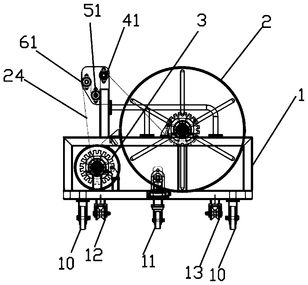
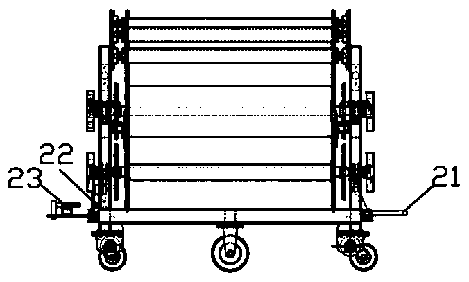
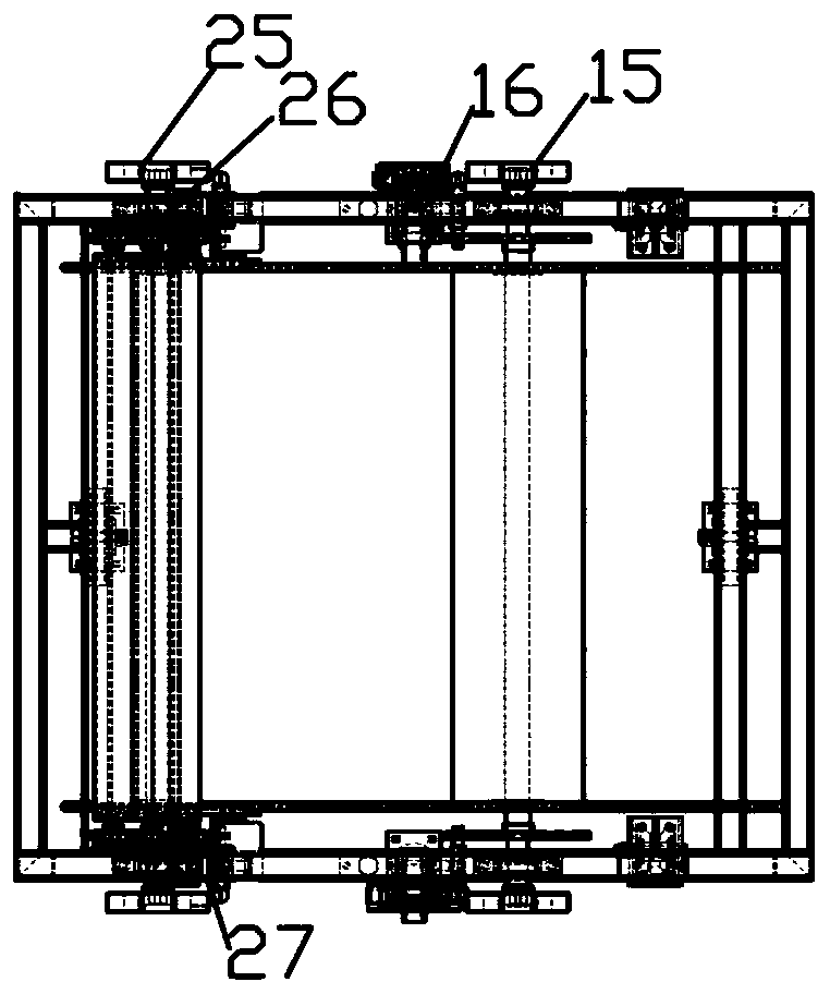
The invention provides a material storage tool coiling trolley device. The device comprises a frame, teflon lining cloth, a large spool, a small spool, a plurality of guide rollers, a transmission assembly, a brake mechanism, a drag hook locking mechanism and a traction pull ring mechanism, wherein the large spool, the small spool, the plurality of guide rollers, the transmission assembly, the brake mechanism, the drag hook locking mechanism and the traction pull ring mechanism are arranged on the frame, trundles and guide rail wheels are arranged at the bottom of the frame, the large spool and the small spool are arranged on the right side and the left side of the frame respectively, the height between a central axis of the large spool and the bottom side of the frame is larger than thatbetween a central axis of the small spool and the bottom side of the frame, the plurality of guide rollers are distributed on the frame in a staggered mode through bearings, the teflon lining cloth isseparated from a film on the large spool and is guided and wound on the small spool through the plurality of guide rollers, the drag hook locking mechanism and the traction pull ring mechanism are arranged on the front side and the rear side of the frame respectively, the transmission assembly comprises a first transmission chuck, a first transmission shaft, a second transmission chuck and a second transmission shaft, wherein the first transmission chuck and the second transmission chuck are in transmission connection with the large spool and the small spool through the first transmission shaft and the second transmission shaft respectively, and the brake mechanism comprises a first brake disc, a first limit rod, a second brake disc and a second limit rod.

Description

technical field [0001] The invention belongs to the field of tire production, and in particular relates to a device for a coiling trolley for a semi-finished inner liner / sidewall storage tooling. Background technique [0002] Our company's original material storage form is the large I-shaped wheel storage and coiling method, which has many inconveniences in operation. Every time the material needs to be rolled, it needs manpower to place the interlining on the take-up frame, and then manually roll the interlining on the large I-shaped wheel before coiling; and the transportation method of the large I-shaped wheel is forklift transportation, which does not affect the material and the I-shaped wheel itself. would have adverse effects. The storage length of the large I-wheel storage and coiling method is short, the quantity used is large, and it takes up a large space. Contents of the invention [0003] In view of the above problems, the present invention provides a coiling...

Claims


Application Information

Patent Timeline
Patent Type & Authority Applications(China)
IPC IPC(8): B65H18/10B65H18/02
Inventor 张春波王维余善康高通
Owner HANGZHOU CHAOYANG RUBBER
Learn More