Underground station exit and entrance structure and construction method thereof

A technology for underground stations and entrances and exits, which is applied in the field of rail transit. It can solve the problems of washing away, structural damage of entrances and exits, and the inability of subway entrances and exits to meet the requirements of anti-scouring, anti-flooding and anti-floating, so as to ensure safety and ensure normal installation.

Pending Publication Date: 2019-06-07
牛斌
View PDF8 Cites 1 Cited by
  • Summary
  • Abstract
  • Description
  • Claims
  • Application Information

AI Technical Summary

Problems solved by technology

Since the design service life of the subway structure is 100 years, the design standard for flood control is generally once in 100 years or once in 200 years. In this case, due to the wandering of the deep groove and the influence of the auxiliary facilities on the ground, the maximum scour depth is generally deeper , conventional subway entrances and exits cannot meet the problems of anti-scouring, anti-flooding and anti-floating
Under the condition of maximum scouring depth, the bottom soil of the conventional entrance and exit structure will be washed away, causing the entrance and exit structure to be damaged or cannot be used normally

Method used


Image

  • Underground station exit and entrance structure and construction method thereof
  • Underground station exit and entrance structure and construction method thereof
  • Underground station exit and entrance structure and construction method thereof

Examples


Embodiment Construction

[0034] In order to make the technical problems, technical solutions and beneficial effects to be solved by the present invention clearer, the present invention will be further described in detail below in conjunction with the accompanying drawings and embodiments. It should be understood that the specific embodiments described here are only used to explain the present invention, not to limit the present invention.

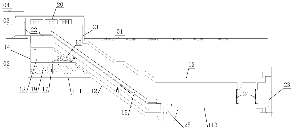
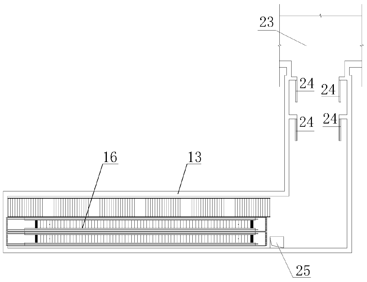
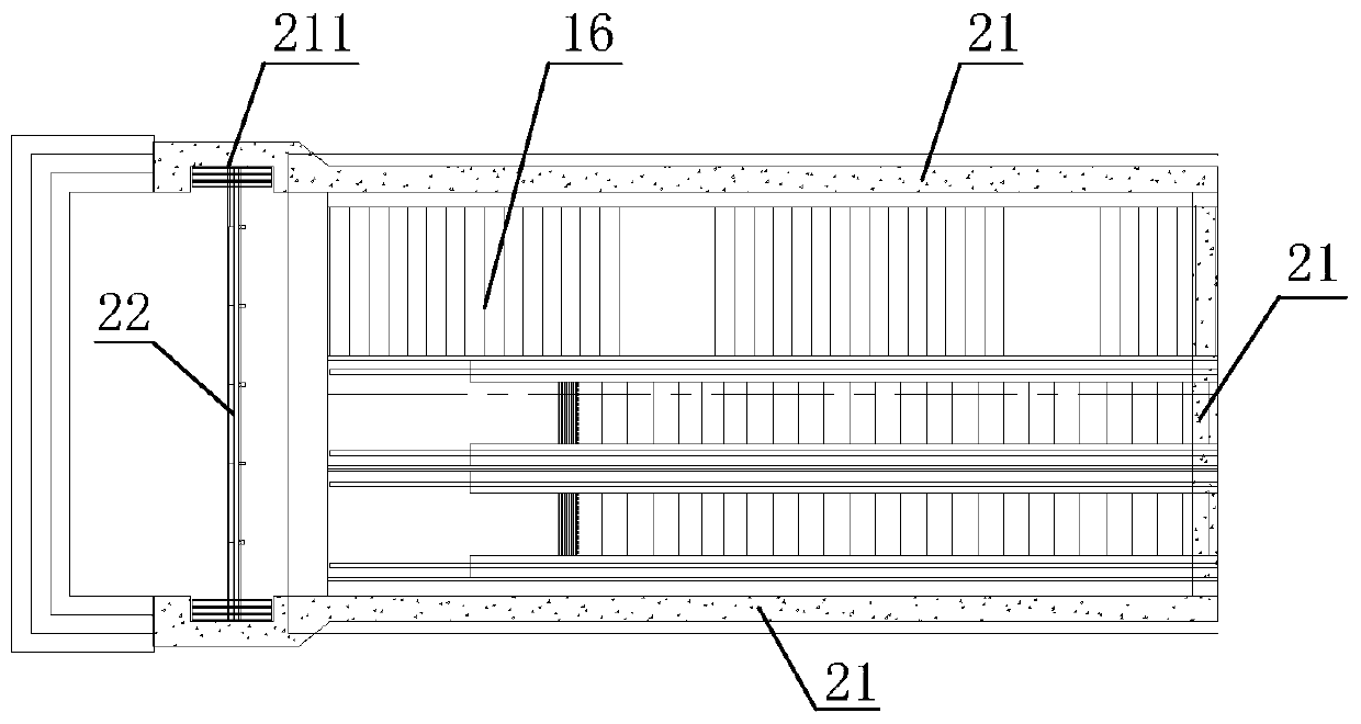
[0035] see Figure 1-Figure 3 , the entrance and exit structure of the underground station provided by the present invention is now described. An entrance and exit structure of an underground station, comprising a bottom plate 11, a top plate 12 and a side wall 13 connecting the bottom plate 11 and the top; The bottom plate is located below the maximum scour depth elevation line 02, and a retaining wall 14 that can form a closed structure is provided between the sinking section 111 and the ground; between the retaining wall 14 and the sinking section, a climbing s...


PUM


Abstract

The invention provides an underground station exit and entrance structure and a construction method thereof, and belongs to the field of rail transit. The underground station exit and entrance structure comprises a bottom plate, a top plate and side walls; the bottom plate comprises a sinking section, a climbing section and a horizontal passage section, wherein the sinking section is positioned below the elevation line of the maximum scouring depth, and a retaining wall capable of forming a closed structure is arranged between the sinking section and the ground; and a supporting surface is arranged between the retaining wall and the sinking section. According to the underground station exit and entrance structure and the construction method thereof, the sinking section, close to the ground, of the bottom plate of the exit and entrance structure is arranged below the elevation line of the maximum scouring depth, and the retaining wall capable of forming the closed structure is arrangedbetween the sinking section and the ground, so that the erosion prevention problem of the exit and entrance structure under a flood working condition is effectively solved, the situation that the bottom plate structure is disengaged and cantilevered due to a soil body under the bottom plate of a conventional exit and entrance structure being scoured by water flow under the maximum scouring depth is avoided, the safety of the exit and entrance structure is ensured, and the underground station exit and entrance structure and the construction method thereof can be applied to the construction of underground stations around flood flowing areas or flood discharge rivers.

Description

technical field [0001] The invention belongs to the technical field of rail transit, and more specifically relates to an entrance and exit structure of an underground station. Background technique [0002] With the rapid development of cities, urban rail transit such as subways and light rails is an effective way to alleviate urban congestion. Due to the shortage of urban land resources, urban rail transit lines such as subways must be installed underground sometimes, and entrances and exits are necessary auxiliary facilities as personnel access channels. If there are rivers around the city, the underground station may be set in the flood discharge area or around the flood discharge river. The flood discharge area refers to the water passing area that does not have water at ordinary times, and when it reaches a certain flood level, part of the flood can be released. In case of a large flood, the flood outlet must be opened according to the specified location and width or t...

Claims


Application Information

Patent Timeline
Patent Type & Authority Applications(China)
IPC IPC(8): E02D29/045E02D31/02
Inventor 牛斌王琦张彦周志龙韩聪聪高世权
Owner 牛斌
Why Eureka
Try Eureka