Telescopic conveying device

A transmission device and telescopic technology, which is applied in the field of telescopic transmission devices, can solve the problems that the transmission device occupies a large space, is difficult to apply to the job site, and has poor flexibility.

Inactive Publication Date: 2019-06-11
上海献怡智能科技有限公司
View PDF0 Cites 2 Cited by
  • Summary
  • Abstract
  • Description
  • Claims
  • Application Information

AI Technical Summary

Problems solved by technology

[0002] In the warehousing and logistics of goods, in order to facilitate the loading and unloading of goods, it is often necessary to use a transmission device. In order to adapt to a longer transmission distance as much as possible, the current transmission device is usually made relatively large, which leads to the large space occupied by the transmission device, and It is difficult to apply to the job site with small space, and the flexibility is poor

Method used


Image

  • Telescopic conveying device
  • Telescopic conveying device
  • Telescopic conveying device

Examples


Embodiment Construction

[0038] For ease of understanding, the present invention will be further described below in conjunction with the accompanying drawings.

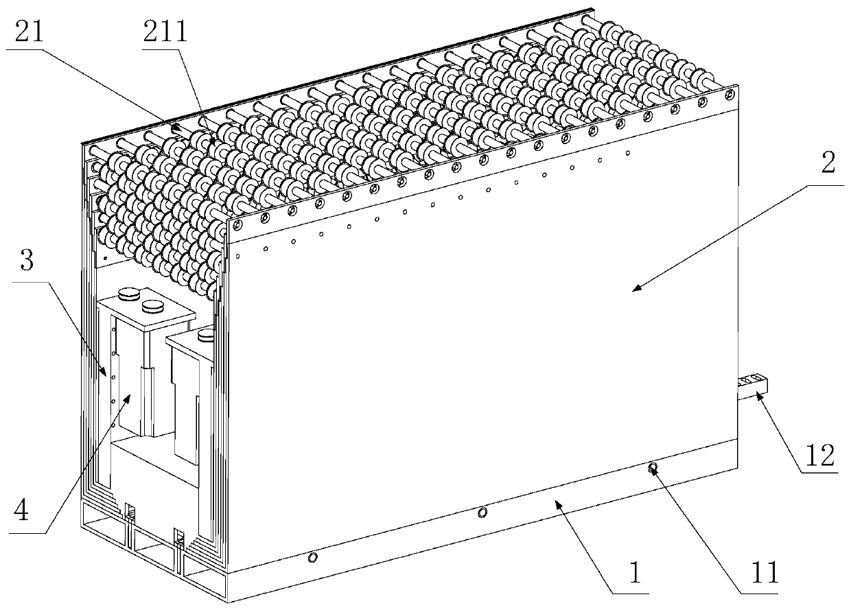
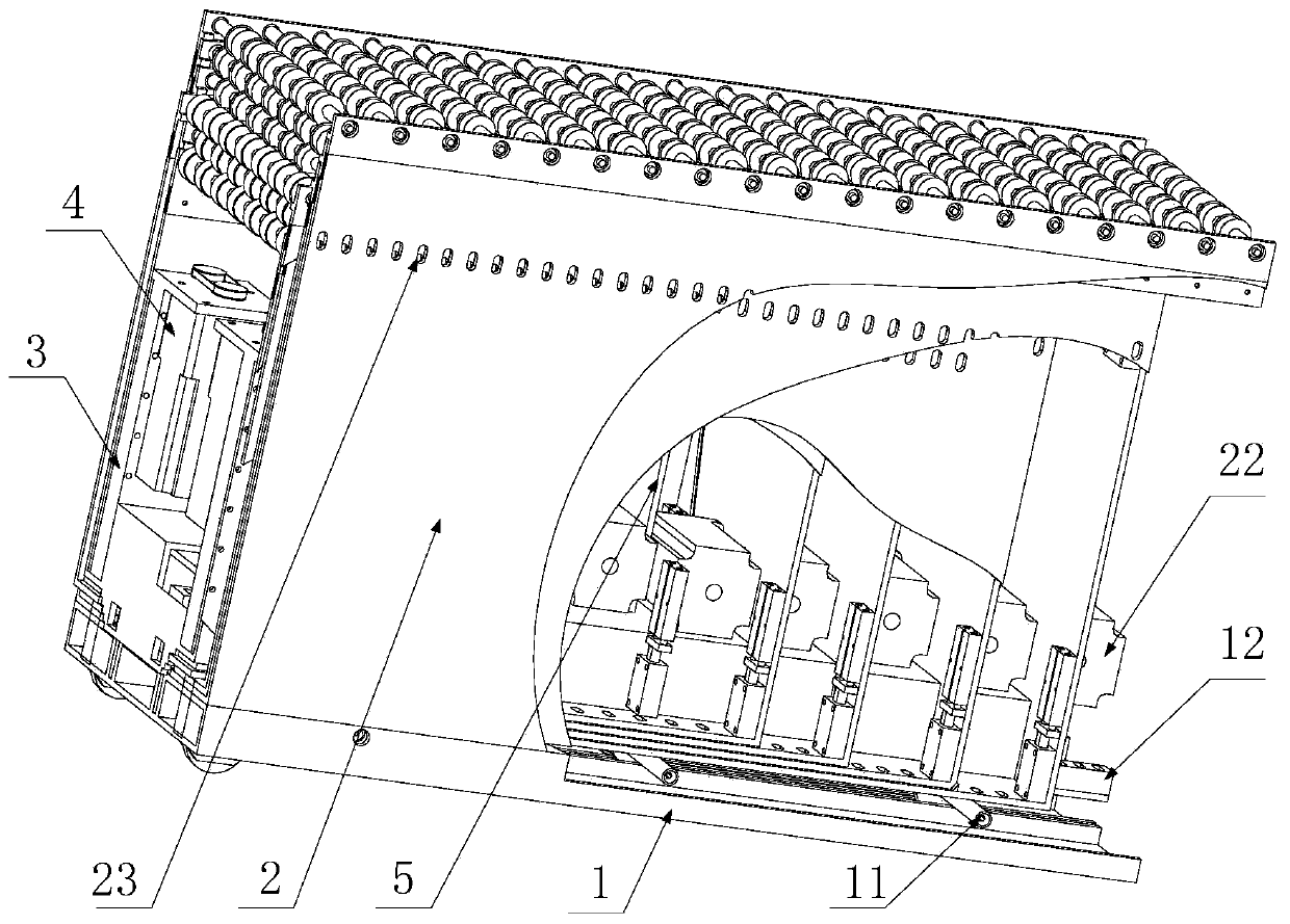
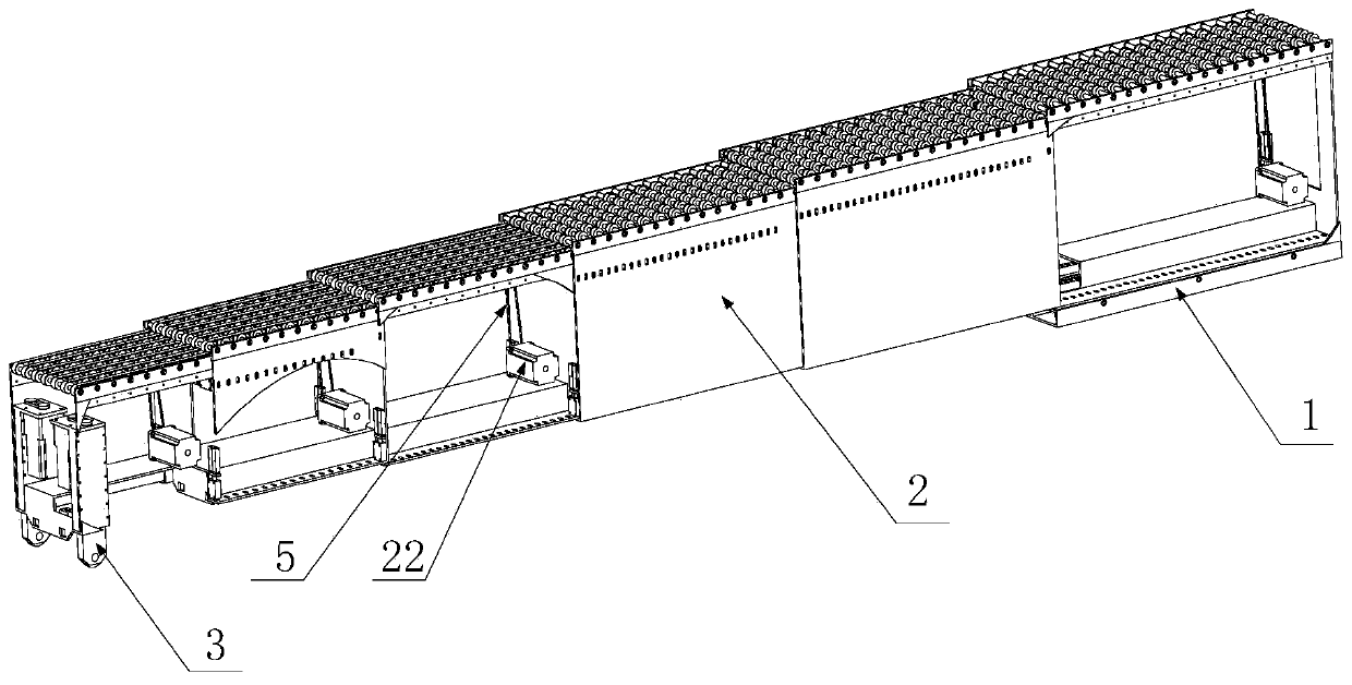
[0039] see Figure 1 ~ Figure 3 , figure 1 It is a schematic diagram of the retracted state of the telescopic conveying device provided by the embodiment of the present invention, figure 2 is a partial cross-sectional view of the retractable conveying device provided by the embodiment of the present invention in a contracted state, image 3 It is a partial cross-sectional view of the telescopic transmission device provided by the embodiment of the present invention in an extended state. The telescopic transmission device provided by the embodiment of the present invention includes a machine base 1 and a plurality of telescopic joints 2, wherein the telescopic joints 2 are box-shaped and are nested together one by one, and the outermost telescopic joint 2 is located at the Above, and fixedly connected with the machine base 1, the machine b...


PUM


Abstract

The invention provides a telescopic conveying device. The telescopic conveying device comprises a base (1) and a plurality of telescopic joints (2); the telescopic joints (2) are gradually connected in a sleeved manner; the telescopic joints (2) are box-body-shaped; erecting side plates are arranged on the two sides of each telescopic joint (2); conveying rollers (21) perpendicular to the side plates are arranged at the tops of the telescopic joints (2); bottom plates fixedly connected with the side plates are arranged at the bottoms of the telescopic joints (2); openings in which adjacent inner layer telescopic joints (2) are sleeved are formed in the front ends of the telescopic joints (2); the outermost telescopic joint (2) is located on the base (1), and is fixedly connected with the base (1); a push-and-pull rail (12) and a driving unit are arranged on the base (1); the push-and-pull rail (12) is in sliding connection with the base (1); and the driving unit is used for driving thepush-and-pull rail (12). Except for the outermost telescopic joint (2), prepositioned electric control plug pins are fixedly installed at the parts, close to the front ends, of the lower surfaces ofthe bottom plates of the other telescopic joints (2); and first pin holes fitting with the prepositioned electric control plug pins are formed in the upper surfaces of the push-and-pull rail (12). Thetelescopic conveying device is flexibly applied into working fields in different space sizes.

Description

technical field [0001] The invention relates to the technical field of transmission devices, in particular to a telescopic transmission device. Background technique [0002] In the warehousing and logistics of goods, in order to facilitate the loading and unloading of goods, it is often necessary to use a transmission device. In order to adapt to a longer transmission distance as much as possible, the current transmission device is usually made relatively large, which leads to the large space occupied by the transmission device, and It is difficult to apply to a job site with a small space, and the flexibility is poor. Therefore, how to improve the conveying device so that it can be flexibly applied to job sites with different sizes has become a technical problem to be solved urgently by those skilled in the art. Contents of the invention [0003] In view of this, the present invention provides a telescopic conveying device, which can be extended and shortened, so it can ...

Claims


Application Information

Patent Timeline
IPC IPC(8): B65G13/12
Inventor 不公告发明人
Owner 上海献怡智能科技有限公司
Why Eureka
Try Eureka