Pad printing device

A technology of pad printing and equipment, applied in printing, printing machines, rotary printing machines, etc., can solve the problems of rubber head deformation, printing quality, adverse effects, etc., and achieve the effect of improving printing quality

Inactive Publication Date: 2017-11-07
KENT ENG GAOYAO
View PDF19 Cites 9 Cited by
  • Summary
  • Abstract
  • Description
  • Claims
  • Application Information

AI Technical Summary

Problems solved by technology

[0006] The technical problem to be solved by the present invention is to provide a kind of pad printing equipment in view of the above-mentioned defects of the prior art, which overcomes that after the existing pad printing equipment adds parts such as a constant temperature control device on (inside) the rubber head, the effect on the rubber head deformation and defects that adversely affect print quality

Method used


Image

  • Pad printing device
  • Pad printing device
  • Pad printing device

Examples


Embodiment 1

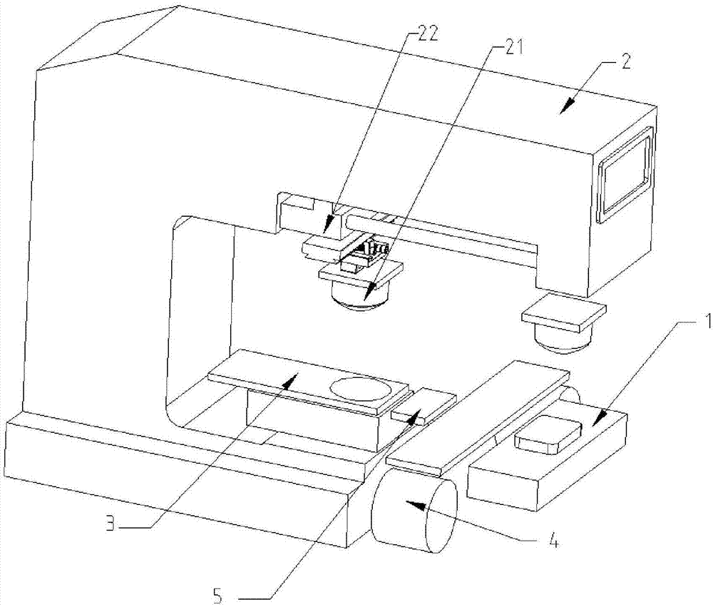
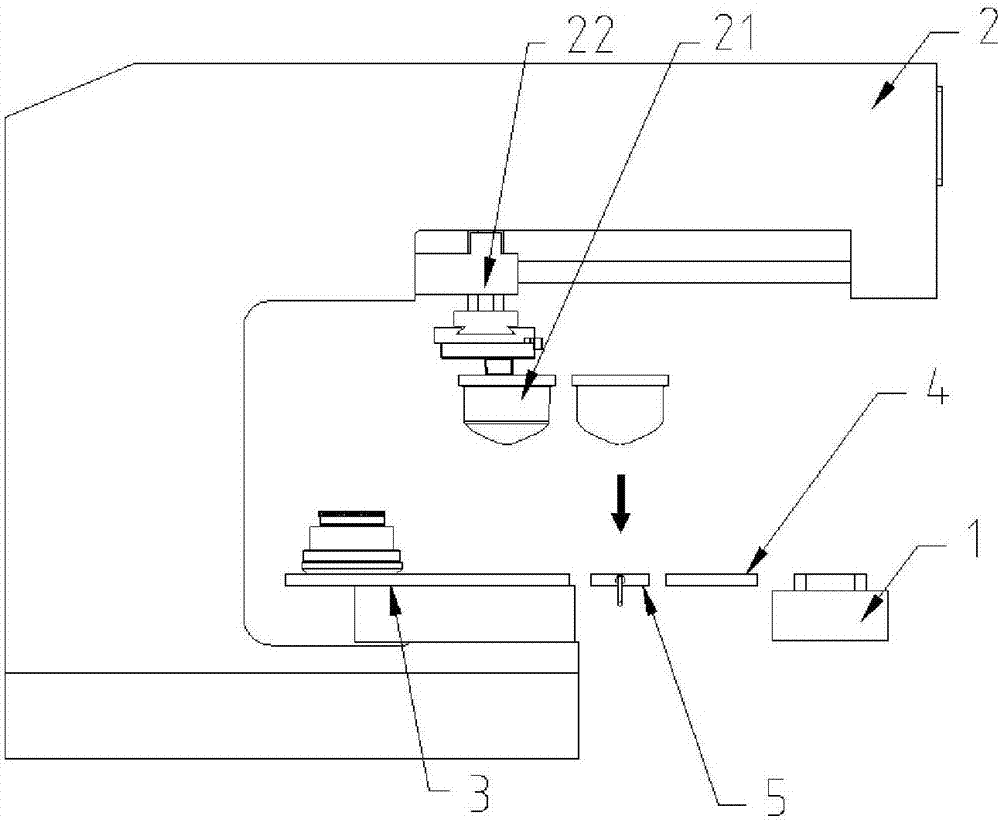
[0025] like figure 1 , 2 As shown, the pad printing equipment of this embodiment includes a pad printing machine head 2 for placing an object to be printed on a workbench 1, a rubber head 21, an ink supply device 3 for providing ink patterns, and a rubber head for cleaning. The cleaning device 4 of 21 further includes a heating device 5 for heating the rubber head 21 before the rubber head 21 dips the ink pattern on the ink supply device 3 . The pad printing equipment of this embodiment is a "bull head type" pad printing equipment, and the pad printing machine head 2 is provided with a push pad 21 on the heating device 5, the ink supply device 3, the workbench 1 and the cleaning device. 4, a shifting mechanism 22 that circulates between 4, the shifting mechanism 22 includes a polished rod horizontally arranged below the pad printing head 2, and a slide seat that is arranged on the polished rod and is driven by an air cylinder (hydraulic cylinder) or a motor to move along the ...

Embodiment 2

[0028] like Figure 5 , 6 As shown, the pad printing equipment of this embodiment includes an ink supply device 3 for providing ink patterns, a cleaning device 4 for cleaning the rubber head 21, and an adjustment platform 6 for placing objects to be printed, and also includes at least A mobile printing device of a glue head 21 and a heating device 5 for heating the glue head 21 before the glue head 21 dips the ink pattern on the ink supply device 3 . By setting the heating device 5, the heating device 5 is used to heat the rubber head 21 before the rubber head 21 dips the ink pattern on the ink supply device 3, thereby realizing the control of the volatilization speed of the ink solvent on the rubber head 21, thereby improving print quality. After the rubber head 21 is heated by the heating device 5 before dipping the ink pattern, the temperature of the surface layer of the rubber head 21 rises, which can ensure that a thicker ink pattern is dipped from the ink supply device...


PUM


Abstract

The invention relates to the field of pad printing, in particular to a pad printing device. The device comprises a workbench used for placing a to-be-printed object, a pad printing head provided with a rubber head, an ink supply device used for providing ink patterns and a cleaning device used for cleaning the rubber head, and further comprises a heating device for heating the rubber head before the rubber head is dipped in and acquire the ink pattern on the ink supply device. According to the pat printing device, by arranging the heating device, the heating device is used for heating the rubber head before the rubber head is dipped in and acquire the ink pattern on the ink supply device to control the volatilization speed of ink solvent on the rubber head, and thus the printing quality is improved. The temperature of the surface layer of the rubber head rises after the heating device heats the rubber head and before the rubber head is dipped in and acquire the ink pattern, a thicker ink pattern is acquired from the ink supply device and the surface layer ink solvent, which is in contact with the rubber head, of the acquired ink pattern is rapidly volatilized to form a colloidal layer, and thus the printing quality can be greatly improved on the premise of not influencing the movement of the rubber head and parts driving the rubber head.

Description

technical field [0001] The invention relates to the field of pad printing, in particular to a pad printing device. Background technique [0002] Pad printing is one of the special printing methods. The most important feature of pad printing is that in addition to conventional flat printing, it can also complete curved surface printing such as concave and convex surfaces. It is a curved rubber head made of silicone rubber material. The ink pattern on the concave plate is dipped on the surface of the rubber head, and then transferred to the printed object. The shape of the rubber head can be adjusted according to the shape of the printed object during printing. Freely change to complete the printing. [0003] The most ideal situation is that all the ink on the gravure plate is transferred to the printed object. During the production process, if the ink layer in contact with the rubber head just forms a gel, the printing quality can be greatly improved. However, if the ink l...

Claims


Application Information

Patent Timeline
Patent Type & Authority Applications(China)
IPC IPC(8): B41F17/00
Inventor 何宏文
Owner KENT ENG GAOYAO
Why Eureka
Try Eureka