
Indoor distance direction moving SAR imaging method based on improved RD algorithm

An imaging method and a range-oriented technology, applied in the field of radar, can solve the problems that the strabismus SAR cannot effectively cover the room, it is difficult to form an aperture, and there is no height, etc., to save time, improve processing speed, and improve efficiency.

Active Publication Date: 2019-06-11
NANJING UNIV OF SCI & TECH
View PDF5 Cites 2 Cited by
  • Summary
  • Abstract
  • Description
  • Claims
  • Application Information

AI Technical Summary

Problems solved by technology

However, due to the complex indoor environment and limited space, the distance that the UAV cannot move in the azimuth direction is limited, which makes it difficult for the traditional squint SAR imaging method to form a large enough aperture; and there is not enough height, so that the squint SAR cannot effectively cover the whole room

Method used


Image

  • Indoor distance direction moving SAR imaging method based on improved RD algorithm
  • Indoor distance direction moving SAR imaging method based on improved RD algorithm
  • Indoor distance direction moving SAR imaging method based on improved RD algorithm

Examples


Embodiment

[0083] Existing SAR imaging methods for detecting targets include the following steps:

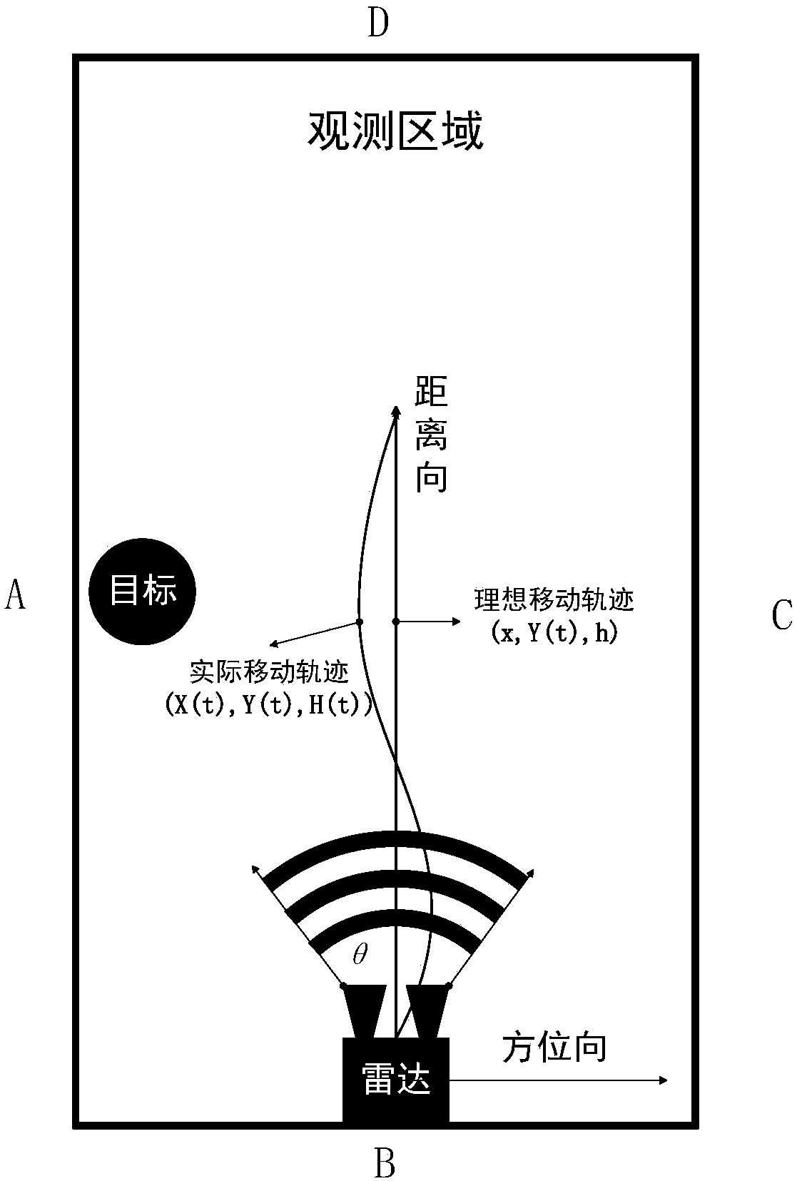
[0084] Step 1. The experimental settings are as follows Figure 4 As shown, the observation area is 4.5m*3.5m, with the position of the radar as the coordinate zero point, the height of the radar is 0.8m, two objects are placed directly in front of the radar, and the position of target A is at (3m, 1, 5m, 0.74m) At , the position of target B is at (0.25m, 2, 4m, 0.83m), and then the radar moves along the direction.

[0085] Step 2, using the traditional SAR method to process the radar signal, can get as follows Figure 5The SAR image shown. It can be seen from the figure that the position of target A is consistent with the theory, but because the radar is obstructed by the wall, it cannot form a large enough aperture to focus on target B close to the wall.

[0086] Therefore, the traditional squint SAR method cannot detect target B.

[0087] The present invention is based on the indoor...


PUM


Abstract

The invention discloses an indoor distance direction moving SAR imaging method based on an improved RD algorithm, which comprises the following steps: firstly, moving an FMCW radar along the distancedirection to obtain a radar echo signal; then, correcting the obtained echo signal according to the moving track to obtain an effective signal; then imaging the signal by using an improved RD algorithm; and finally, performing geometric transformation to obtain a real SAR image. The indoor distance direction moving SAR imaging method is effective and feasible, has reliable performance, and can accurately locate objects at the edge or corner of the indoor wall in a narrow environment.

Description

technical field [0001] The invention belongs to the technical field of radar, and in particular relates to an indoor range-moving SAR imaging method based on an improved RD algorithm. Background technique [0002] Synthetic aperture radar (SAR) uses the radar antenna to move upward in azimuth over the target area to synthesize a larger aperture and achieve better spatial resolution than traditional beam scanning radar. Traditional SAR systems need to be carried on aircraft or satellites to obtain SAR images of the earth's surface. The rapid development of UAVs and the fact that FMCW radars have become more portable and lower cost have made it possible for UAVs to carry FMCW radars to implement SAR systems. [0003] However, at present, the combination of drones and radars is still in an outdoor environment. UAVs are used to carry radars to scan a large synthetic aperture in azimuth, and then achieve high resolution in azimuth through coherent processing Doppler modulation. ...

Claims


Application Information

Patent Timeline
Patent Type & Authority Applications(China)
IPC IPC(8): G01S13/90G01S7/41
Inventor 李彧晟胡家铭洪弘顾陈孙理闫嘉明熊俊军马悦朱晓华
Owner NANJING UNIV OF SCI & TECH
Learn More