High-resolution fundus optical imaging system

An optical imaging system and high-resolution technology, applied in the field of high-resolution fundus optical imaging system, achieves the effects of high practicability, reduction of ghost images, and simple structure

Active Publication Date: 2022-07-12
南京览视医疗科技有限公司
View PDF13 Cites 0 Cited by
  • Summary
  • Abstract
  • Description
  • Claims
  • Application Information

AI Technical Summary

Problems solved by technology

[0007] Aiming at the problem that the field of view of traditional fundus imaging systems is generally relatively small, mostly around 40°, the fundus optical imaging system provided by the present invention has a system field of view of 50° and a resolution of object space of up to 0.185mm; for traditional fundus imaging systems The structure of the imaging system is complex and the diopter compensation range is insufficient. The fundus optical imaging system provided by the present invention has a diopter adjustment range of -20D~+20D, a wide compensation range, and meets the diopter adjustment of most human eyes.

Method used


Image

  • High-resolution fundus optical imaging system
  • High-resolution fundus optical imaging system
  • High-resolution fundus optical imaging system

Examples


Embodiment 1

[0063] In embodiment 1, the optical imaging system parameters satisfy the following table:

[0064] Table 1 Parameter conditions of the system in Example 1

[0065]

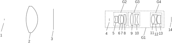
[0066] In addition, f1=27.672 mm; f=-8.300; fov=50°; TTL=200 mm; TTL1=77 mm; d=10.263 mm; FNO=5.922

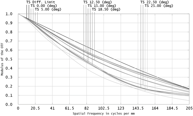
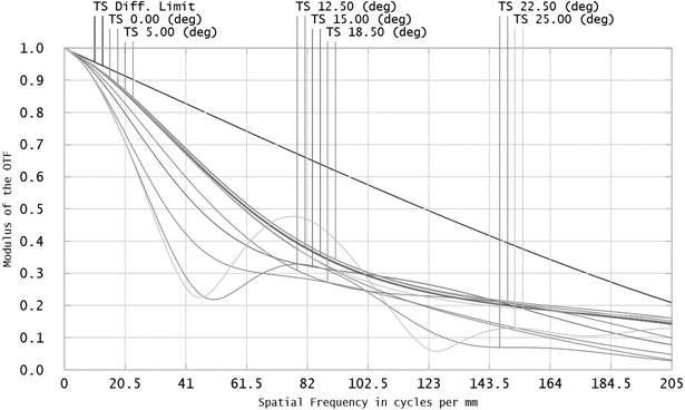
[0067] figure 2 — Figure 4 The MTF curves of Example 1 at 0D, -20D, and +20D diopter are listed respectively. It can be seen from the figure that the maximum field of view of the system is 50°, and the zero field of view, MTF≥0.1@205lp / mm; half Field of view, MTF≥0.1@120lp / mm; full field of view, MTF≥0.1@80lp / mm. The smallest resolvable fundus 0.13μm blood vessel details. The object-side resolution of the system in this embodiment can reach 0.185mm. Due to the imaging magnification effect of the human eye, the minimum 0.13μm blood vessel details of the fundus can be resolved, and high-resolution imaging can be achieved.

Embodiment 2

[0069] In embodiment 2, the optical imaging system parameters satisfy the following table:

[0070] Table 2 Parameter conditions of the system in Example 2

[0071]

[0072] In addition, f1=25.639 mm; f=-8.300; fov=50°; TTL=195 mm; TTL1=75 mm; d=9.562 mm; FNO=5.918

[0073] Figure 5 — Figure 7 The MTF curves of Example 2 at 0D, -20D, and +20D diopter are listed respectively. It can be seen from the figure that the maximum field of view of the system is 50°, and the zero field of view, MTF≥0.1@205lp / mm; half Field of view, MTF≥0.1@120lp / mm; full field of view, MTF≥0.1@80lp / mm. The smallest resolvable fundus 0.13μm blood vessel details can achieve high-resolution imaging.

Embodiment 3

[0075] In embodiment 3, the optical imaging system parameters satisfy the following table:

[0076] Table 3 Parameter conditions of the system in Example 3

[0077]

[0078] In addition, f1=24.855 mm; f=-8.300; fov=50°; TTL=205 mm; TTL1=85 mm; d=9.622 mm; FNO=5.920

[0079] Figure 8 — Figure 10 The MTF curves of Example 3 at 0D, -20D, and +20D diopter are listed respectively. It can be seen from the figure that the maximum field of view of the system is 50°, and zero field of view, MTF≥0.1@205lp / mm; half Field of view, MTF≥0.1@120lp / mm; full field of view, MTF≥0.1@80lp / mm. The smallest resolvable fundus 0.13μm blood vessel details can achieve high-resolution imaging.


PUM


Abstract

The invention discloses a high-resolution fundus optical imaging system, and belongs to the technical field of optical imaging. The system comprises a plurality of lenses and an aperture diaphragm, and sequentially comprises an eye objective lens and a secondary imaging group G1 from an object side to an image side, the secondary imaging group G1 is composed of an aperture diaphragm, a fixed lens group G2, a focusing lens group G3 and a compensating lens group G4, the fixed lens group G2, the focusing lens group G3 and the compensating lens group G4 are respectively composed of a plurality of lenses, the focal length of the fixed lens group G2 is f2, the focal length of the compensating lens group G4 is f3, the focal length of the whole system is f, and the following relational expression needs to be met: 26.149 < = f2 / f < = 40.223; f3 / f is greater than or equal to-12.117 and less than or equal to-8.817. The diopter adjusting range can reach-20D to + 20D, the system field angle is 50 degrees, the object space resolution can reach 0.185 mm, high-resolution imaging is achieved, and obtained fundus image information is clearer and richer.

Description

technical field [0001] The present invention relates to the technical field of optical imaging, in particular, to a fundus imaging optical imaging system technology, and more specifically, to a high-resolution fundus optical imaging system. Background technique [0002] The human eye is a sophisticated optical imaging system, and the retina is equivalent to the receiver in the optical imaging system, which is crucial for acquiring external information. Therefore, the retina is the only tissue in the whole body that can observe blood vessels and their distribution under living and non-invasive conditions. , has become an important window for the diagnosis of eye diseases and related systemic diseases. Fundus imaging is to take pictures of the retinal tissue of the fundus. This method can not only detect common ophthalmic diseases such as cataract and glaucoma, but also diagnose early systemic diseases such as hypertension and diabetes. [0003] Traditional fundus imaging sys...

Claims


Application Information

Patent Timeline
Patent Type & Authority Applications(China)
IPC IPC(8): A61B3/12A61B3/14G02B13/18G02B13/06
CPCA61B3/12A61B3/14G02B13/006G02B13/0045G02B13/06
Inventor 石芬瑜张凯迪沈小厚
Owner 南京览视医疗科技有限公司
Why Eureka
Try Eureka