Lifting device, fire fighting device and mechanical equipment thereof

A lifting device and cable mechanism technology, applied in the direction of cranes, hoisting devices, hoisting equipment braking devices, etc., can solve the problems of not installing fire cannons and other fire-fighting devices, unable to extinguish them in time, and limited cantilever length, etc., to achieve expansion The effect of fire-fighting operation range, improvement of lifting operation range, and high fire extinguishing efficiency

Pending Publication Date: 2019-06-14
CHANGSHA ZHONGLIAN HENGTONG MACHINERY
View PDF0 Cites 1 Cited by
  • Summary
  • Abstract
  • Description
  • Claims
  • Application Information

AI Technical Summary

Problems solved by technology

Its metal structure is like a door-shaped frame. Two legs are installed under the main beam, which can directly walk on the ground track. The two ends of the main beam can have outrigger cantilever beams, but the existing cantilever beams are fixed structures. The length of th

Method used


Image

  • Lifting device, fire fighting device and mechanical equipment thereof
  • Lifting device, fire fighting device and mechanical equipment thereof
  • Lifting device, fire fighting device and mechanical equipment thereof

Examples


Embodiment 1

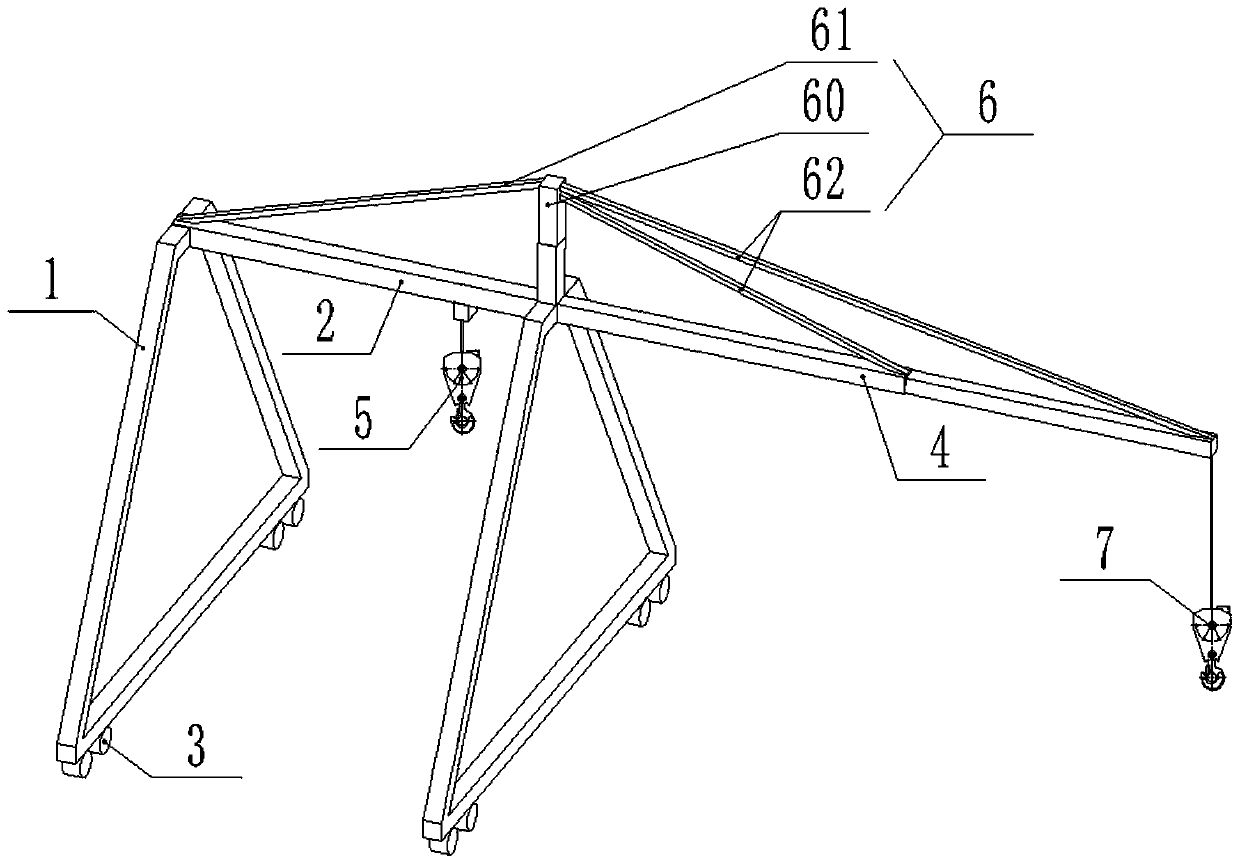
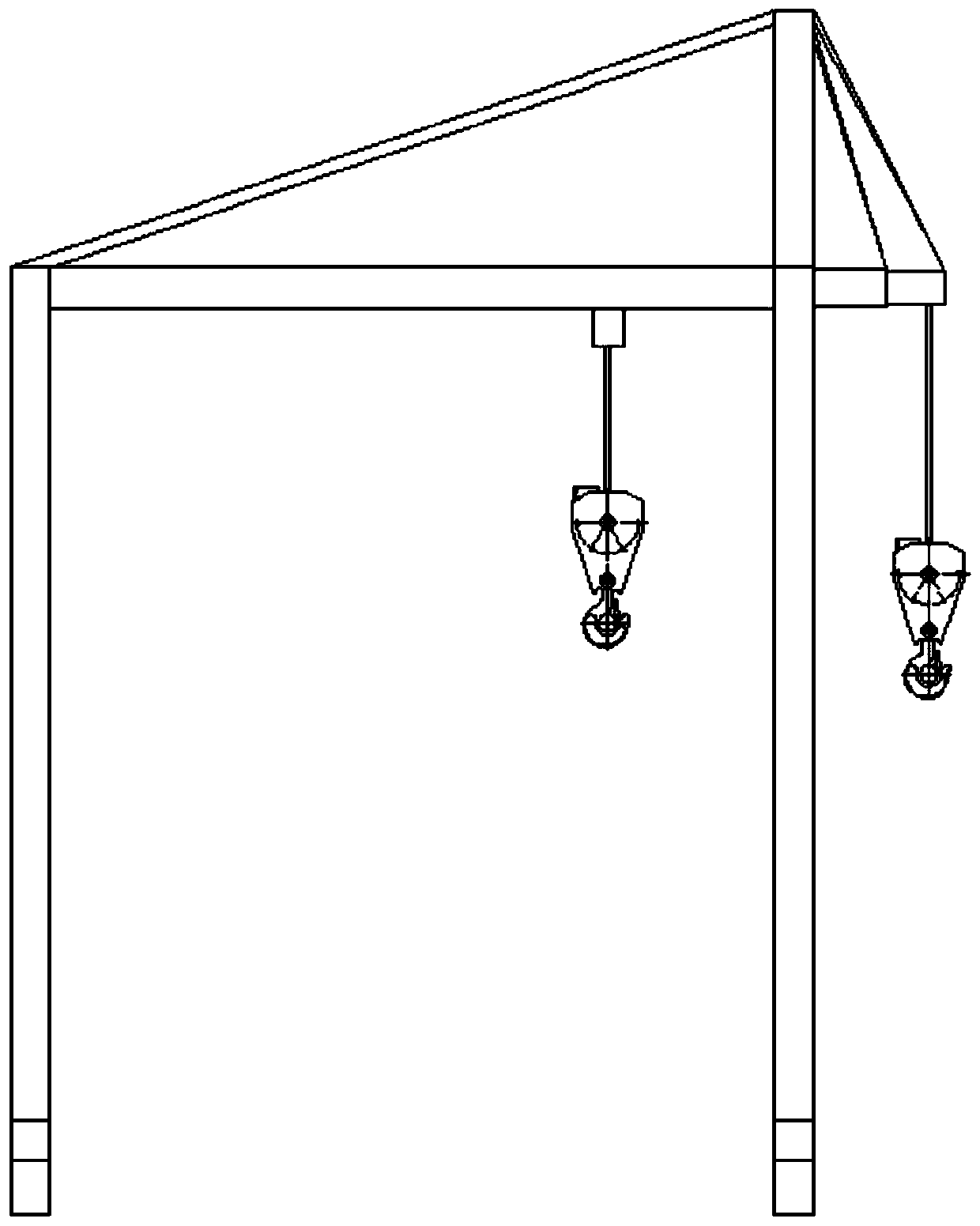
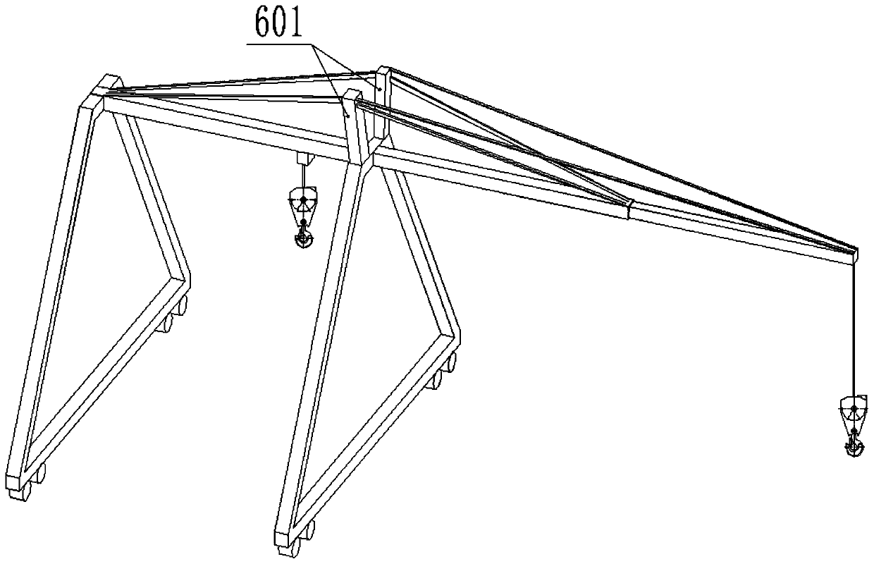
[0021] Such as Figure 1-3 As shown, a lifting device provided in this embodiment includes a beam 2, a pillar 1 and a walking mechanism 3, the two ends of the beam 2 are connected with the pillar 1; the bottom of the pillar 1 is connected with the Walking mechanism 3; described hoisting device also comprises cantilever telescoping mechanism 4, super-lifting cable mechanism 6 and mobile hoisting mechanism 5; Described cantilever telescoping mechanism 4 is located in described crossbeam 2, and Can be retracted and extended, the cantilever telescopic mechanism 4 is connected to the pillar 1 through the super-lifting cable mechanism 6; When hoisting, the mobile hoisting mechanism 5 moves along the crossbeam 2 or the cantilever telescopic mechanism 4 moves, thereby realizing hoisting in place at different working positions.

[0022] In this embodiment, on the basis of the traditional gantry crane, a cantilever telescopic mechanism 4 is added in the beam 2. The cantilever telescopi...

Embodiment 2

[0032] Embodiment 2 On the basis of Embodiment 1, further, a fire-fighting mechanism (not shown in the figure) is connected to the cantilever telescopic mechanism 4 . Under the action of the fire-fighting mechanism, the function of fire-fighting and fire-extinguishing can be realized, and the practicability of this embodiment can be improved. And under the effect of the cantilever telescopic mechanism 4, the fire-fighting operation range of the fire-fighting mechanism is expanded, and the fire-extinguishing efficiency is high. In this embodiment, the fire-fighting mechanism includes a fire-fighting monitor and a pipeline connected with the fire-fighting monitor, which can be selected from existing products, wherein the number of fire-fighting monitors is one or more, and multiple fire-fighting monitors are respectively arranged on the cantilever telescopic mechanism 4 Proper location to improve fire extinguishing efficiency. Wherein the fire-fighting mechanism requires that t...


PUM


Abstract

The invention discloses a lifting device. The lifting device comprises a cross beam, supporting columns, walking mechanisms, a cantilever telescopic mechanism, a super-lift cable pulling mechanism anda movable hanging mechanism, wherein the supporting columns are connected to the two ends of the cross beam; the walking mechanisms are connected to the bottoms of the supporting columns; the cantilever telescopic mechanism is arranged in the cross beam, and can be retracted and extended relative to the cross beam, and the cantilever telescopic mechanism is connected with the supporting columns through the super-lift cable mechanism; and the movable hanging mechanism is movably arranged on the cross beam and the cantilever telescopic mechanism. The lifting device is wide in operation range, flexible and convenient to use and has a fire extinguishing function.

Description

technical field [0001] The invention relates to the technical field of engineering machinery, in particular to a lifting device, a fire fighting device and mechanical equipment thereof. Background technique [0002] Gantry crane is a kind of deformation of bridge crane, also called gantry crane, which is mainly used for loading and unloading operations of outdoor cargo yard, material yard cargo and bulk cargo. Gantry cranes have the characteristics of high site utilization, large operating range, wide adaptability, and strong versatility, and are widely used in port freight yards. Its metal structure is like a door-shaped frame. Two legs are installed under the main beam, which can directly walk on the ground track. The two ends of the main beam can have outrigger cantilever beams, but the existing cantilever beams are fixed structures. The length of the cantilever The scope of work is limited, the scope of work is small, the use is restricted, and the current crane only ha...

Claims


Application Information

Patent Timeline
IPC IPC(8): B66C25/00B66C5/00
Inventor 张良张建军李义涂凌志
Owner CHANGSHA ZHONGLIAN HENGTONG MACHINERY
Why Eureka
Try Eureka