Novel cap screwing machine

A capping machine and a new type of technology, applied in screw caps and other directions, can solve the problems of the bottle not being capped, the guide plate is bumpy, the bottle is broken, etc. falling effect

Inactive Publication Date: 2019-06-14
南通博琅机械科技有限公司
View PDF0 Cites 0 Cited by
  • Summary
  • Abstract
  • Description
  • Claims
  • Application Information

AI Technical Summary

Problems solved by technology

When the existing conveying device transports the bottle, the support at the lower part of the guide plate is an elastic support, so that the guide plate is bumped, and the bottle is prone to the phenomenon that the bottle cannot be covered or the bottle is broken

Method used


Image

  • Novel cap screwing machine

Examples


Embodiment Construction

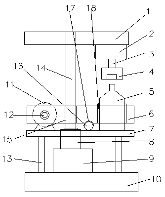
[0009] Such as figure 1 As shown, the new capping machine includes a base 10, the base 10 is connected to the guide plate 7 through the column 13; the base 10 is provided with a lifting cylinder 9, and the lifting cylinder 9 is connected to the telescopic rod 14 through the telescopic sleeve 8; the telescopic sleeve 8 passes through the guide plate 7, two The upper end face of the person is flush; the telescopic rod 14 passes through the bearing 15 located on the rotating plate 6; one end of the rotating plate 6 is fixedly connected with the telescopic rod 12 of the electric telescopic rod 11; the other end is provided with a ball 16; One end of the guide plate 7, the other end of the guide plate 7 places the bottle 5; the top of the bottle 5 is provided with a screw cap 4, the screw cap 4 is connected with the motor 2 through the connecting shaft 3, the motor 2 is fixed on the support plate 1, and the support plate 1 is fixed with the telescopic rod 14 connect.

[0010] The ...


PUM


Abstract

A novel cap screwing machine comprises a base (10), and the base (10) is connected with a guide plate (7) through a stand column (13). A lifting air cylinder (9) is arranged on the base (10), and thelifting air cylinder (9) is connected with a telescopic rod (14) through a telescopic sleeve (8). The telescopic sleeve (8) penetrates through the guide plate (7). The telescopic rod (14) penetrates through a bearing (15) arranged on a rotary plate (6). One end of the rotary plate (6) is fixedly connected with a telescopic rod (12) of an electric telescopic rod (11). A ball (16) is arranged at theother end of the rotary plate (6). The electric telescopic rod (11) is fixedly arranged at one end of the guide plate (7), and a bottle (5) is placed at the other end of the guide plate (7). A rotarycap (4) is arranged above the bottle (5), and connected with a motor (2) through a connecting shaft (3), the motor (2) is fixed to a supporting plate (1), and the supporting plate (1) is fixedly connected with the telescopic rod (14). According to the novel cap screwing machine, the problems that during cap screwing, the bottle is missed to be covered with the cap, and the bottle is likely to drop are effectively solved.

Description

technical field [0001] The invention relates to a novel capping machine. Background technique [0002] Capping machine, also called capping machine, capping machine or capping machine, is mainly used for plastic bottles and glass bottles. When the existing conveying device transports bottles, the support at the lower part of the guide plate is an elastic support, so that the guide plate is bumped, and the bottle is prone to the phenomenon that the bottle cannot be covered or the bottle is broken. Contents of the invention [0003] In order to solve the above technical problems, the present invention provides a new type of capping machine, including a base, the base is connected to the guide plate through a column; the base is provided with a lifting cylinder, and the lifting cylinder is connected to the telescopic rod through a telescopic sleeve; the telescopic sleeve passes through the guide plate, and the upper ends of the two are flush The telescopic rod passes through...

Claims


Application Information

Patent Timeline
Patent Type & Authority Applications(China)
IPC IPC(8): B67B3/20
Inventor 徐学东
Owner 南通博琅机械科技有限公司
Why Eureka
Try Eureka