Sensory control type motor lock

A sensor control and motor lock technology, which is applied to non-mechanical transmission-operated locks, timing locks, building locks, etc., can solve the problem that the structure for detecting the position of the lock tongue cannot be directly applied, and achieve the effect of ensuring normal operation

Pending Publication Date: 2019-06-14
程倩雁
View PDF3 Cites 2 Cited by
  • Summary
  • Abstract
  • Description
  • Claims
  • Application Information

AI Technical Summary

Problems solved by technology

[0005] However, the structure for detecting the position of the deadbolt in the above technical solutions cannot be directly applied to all situations, and corresponding detection structures need to be designed according to different situations

Method used


Image

  • Sensory control type motor lock
  • Sensory control type motor lock
  • Sensory control type motor lock

Examples


Embodiment

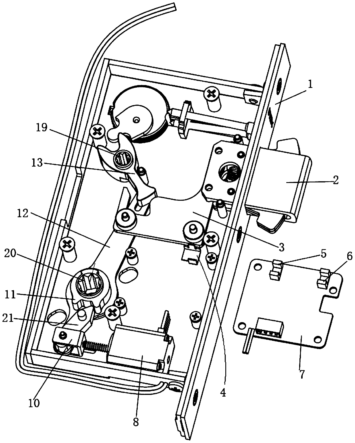
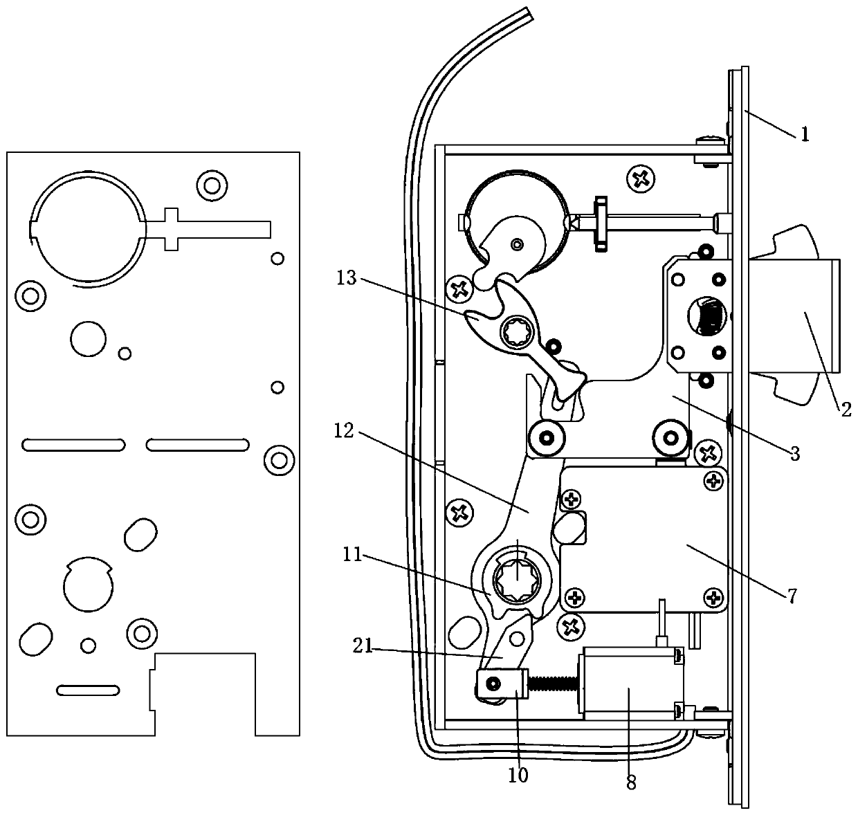
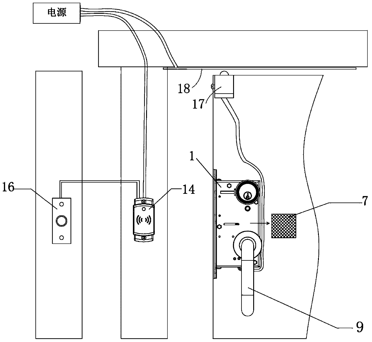
[0049] Such as Figure 1 to Figure 4 As shown, the sensor-controlled motor lock of the present embodiment includes a lock housing 1, and the lock housing 1 is provided with a motor 8, a transmission mechanism, a dead bolt 2, and a control panel 7, and the side of the lock housing 1 is provided with a lock tongue 2 The through hole for entering and exiting; the transmission mechanism includes a push piece 3 connected to the motor 8, and the push piece 3 is fixedly connected with the dead bolt 2; the control board 7 has a controller and a group of sensors, and the signal output terminal of the sensor is connected to the signal input of the controller end connection; push piece 3 has a detection piece 4 matched with the sensor; the controlled end of the motor 8 is connected with the control end of the controller.

[0050] The sensors include a first sensor 5 and a second sensor 6; on this basis, the motor lock has the following specific states:

[0051] (1) When the dead bolt 2 ...


PUM


Abstract

The invention relates to a sensory control type motor lock. The sensory control type motor lock comprises a lock case. The lock case is internally provided with a motor, a transmission mechanism, a lock tongue and a control panel. The side face of the lock case is provided with a through hole for the lock tongue to get in and out. The transmission mechanism comprises a pushing slice which is in transmission connection with the motor, and the pushing slice is fixedly connected with the lock tongue. The control panel is provided with a controller and a set of sensors, and the signal output endsof the sensors are connected with the signal input end of the controller. The pushing slice is provided with a detection slice matched with the sensors. The controlled end of the motor is connected with the control end of the controller. According to the sensory control type motor lock, the position state of the lock tongue can be effectively detected, and then normal running of the motor lock isensured.

Description

technical field [0001] The invention relates to a sensor-controlled motor lock, which belongs to the technical field of electronic locks. Background technique [0002] As far as the inventor knows, the usual transmission mode of the motor lock is: the motor rotates the driving lever through the transmission system, and the driving lever drives the pushing part on the dead bolt to move the dead bolt; At the end of the fork shaft, turn the lever shaft to drive the lock tongue to move. [0003] After searching, it was found that in the Chinese invention patent application with application number CN201610046198.6, application publication number CN106401304A, and titled "A Motor Lock", the device includes a motor, a lock bolt, a lock plate, a lock cylinder, a door position sensor, and a lock bolt The position sensor, the control unit, and the motor lock include two independent transmission systems, the key drive and the motor drive, which are connected to the same deadbolt conne...

Claims


Application Information

Patent Timeline
Patent Type & Authority Applications(China)
IPC IPC(8): E05B47/00E05B43/00E05B15/00G07C9/00
Inventor 程倩雁
Owner 程倩雁
Why Eureka
Try Eureka