Position determining method and device, storage medium and processor

A technology for determining a method and a target position, which is applied in the computer field and can solve problems such as low position accuracy of a capture device

Active Publication Date: 2019-06-14
上海明胜品智人工智能科技有限公司
View PDF11 Cites 15 Cited by
  • Summary
  • Abstract
  • Description
  • Claims
  • Application Information

AI Technical Summary

Problems solved by technology

[0005] The main purpose of the present invention is to provide a position determination method, device, storage medium and processor, to at least solve the technical problem of low accuracy in determining the position of the capture device

Method used


Image

  • Position determining method and device, storage medium and processor
  • Position determining method and device, storage medium and processor
  • Position determining method and device, storage medium and processor

Examples


Embodiment 1

[0038] The embodiment of the present invention provides a position determination method.

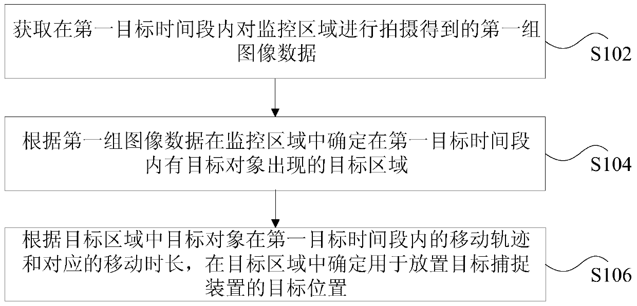
[0039] figure 1 It is a flowchart of a method for determining a position according to an embodiment of the present invention. Such as figure 1 As shown, the method includes the following steps:

[0040] Step S102: Acquire a first set of image data obtained by photographing the monitored area within the first target time period.

[0041] In the technical solution provided in step S102 of the present application, the first set of image data obtained by shooting the monitored area within the first target time period can be acquired through the data acquisition module in the dining scene.

[0042] The dining scene in this embodiment may be a scene with high requirements for food hygiene, may be a dining scene in a public operation place, or a dining scene in home life, and there is no restriction here.

[0043] The data collection module of this embodiment may be a video surveillance device, for exam...

Embodiment 2

[0138] The technical solution of the present invention will be illustrated below in conjunction with preferred embodiments. Specifically, the target object is a pest for illustration.

[0139] This embodiment uses digital technology to assist and guide pest control, rodent prevention, and rodent control in the catering scene, to ensure that key places and facilities in the catering industry are not attacked by pests and rodents, and to guide conventional pest control work Development. Among them, dining scenes can be scenes that focus on food safety, such as restaurants and kitchens.

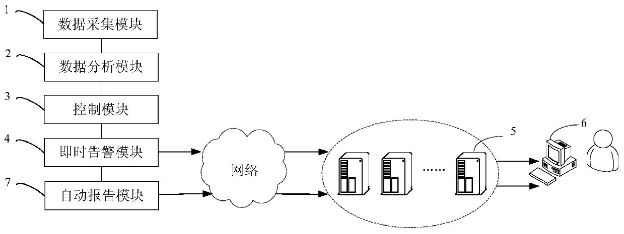
[0140] figure 2 It is a schematic diagram of a target object monitoring system according to an embodiment of the present invention. Such as figure 2 As shown, the system includes: a data acquisition module 1, a data analysis module 2, a control module 3, an instant alarm module 4, a server 5, a terminal 6, and an automatic report module 7.

[0141] The data collection module 1 of this embodiment m...

Embodiment 3

[0186] The embodiment of the present invention also provides a position determining device. It should be noted that the position determining apparatus of this embodiment can be used to execute the position determining method of the embodiment of the present invention.

[0187] Picture 9 It is a schematic diagram of a position determining device according to an embodiment of the present invention. Such as Picture 9 As shown, the device includes: an acquiring unit 10, a first determining unit 20, and a second determining unit 30.

[0188] The acquiring unit 10 is configured to acquire a first set of image data obtained by photographing the monitored area within the first target time period.

[0189] The first determining unit 20 is configured to determine a target area where a target object appears in the first target time period in the monitored area according to the first set of image data.

[0190] The second determining unit 30 is configured to determine a target position for pla...


PUM


Abstract

The invention discloses a position determination method and device, a storage medium and a processor. The method comprises the following steps of acquiring a first group of image data obtained by shooting a monitoring area in a first target time period; determining a target area where the target object appears in the first target time period in the monitoring area according to the first group of image data; and according to the moving track of the target object in the target area in the first target time period and the corresponding moving duration, determining a target position for placing atarget capturing device in the target area, the target capturing device being used for capturing the target object. According to the invention, the effect of improving the accuracy of determining theposition of the capturing device is achieved.

Description

Technical field [0001] The present invention relates to the field of computers, and in particular, to a position determination method, device, storage medium and processor. Background technique [0002] At present, in the prevention and treatment of target objects, it is mainly dependent on the professional experience and subjective judgment of the prevention and treatment personnel to determine the location of the capture tool used to capture the target object in the prevention area. For example, the target object is a mouse, and the capture tool is a mouse sticky board. The prevention and control staff can deploy the sticky mouse board along the walls and corners of the room by observing the excrement of the mouse, the traces of gnawing, and the traces of infestation. [0003] However, when the control personnel are not experienced enough, or the control personnel and the management personnel of the control area do not communicate sufficiently, it is difficult to ensure the accur...

Claims


Application Information

Patent Timeline
Patent Type & Authority Applications(China)
IPC IPC(8): G06T7/246G06T7/73H04N7/18
Inventor 臧云波鲁邹尧吴明辉
Owner 上海明胜品智人工智能科技有限公司
Why Eureka
Try Eureka