
Screw limiting device

A limit device and screw technology, which is applied to screwdrivers, wrenches, manufacturing tools, etc., can solve the problems of inconvenient operation, screw loading and inclination, etc., and achieve the effect of preventing finger injuries, preventing nail deviation, and preventing inclination

Inactive Publication Date: 2019-06-18
新昌县洪涛装饰工程有限公司
View PDF0 Cites 0 Cited by
  • Summary
  • Abstract
  • Description
  • Claims
  • Application Information

AI Technical Summary

Problems solved by technology

[0002] Screws are commonly used in machinery, electrical appliances and buildings, and are widely used; in the prior art, in the process of nailing screws, the situation of screw fixing tilt and inconvenient operation often occurs, and the present invention makes improvements to solve this problem

Method used


Image

  • Screw limiting device
  • Screw limiting device

Examples


Embodiment Construction

[0024] It should be noted that, in the case of no conflict, the embodiments of the present invention and the features in the embodiments can be combined with each other.

[0025] In describing the present invention, it should be understood that the terms "center", "longitudinal", "transverse", "upper", "lower", "front", "rear", "left", "right", " The orientations or positional relationships indicated by "vertical", "horizontal", "top", "bottom", "inner" and "outer" are based on the orientations or positional relationships shown in the drawings, and are only for the convenience of describing the present invention and Simplified descriptions, rather than indicating or implying that the device or element referred to must have a particular orientation, be constructed and operate in a particular orientation, and thus should not be construed as limiting the invention. In addition, the terms "first", "second", etc. are used for descriptive purposes only, and should not be understood ...


PUM


Abstract

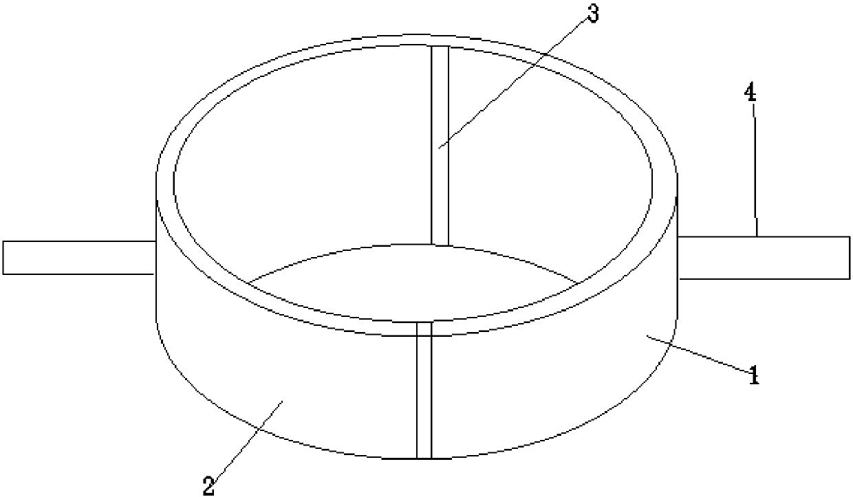
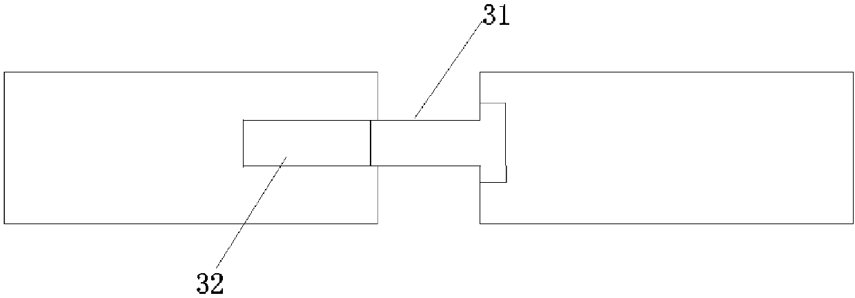
The invention provides a screw limiting device. A screw casing pipe and handrails are included. The handrails are symmetrically arranged on the outer surface of the screw casing pipe. The screw casingpipe is a hollow cylinder and comprises an upper casing pipe body and a lower casing pipe body. Connecting mechanisms are arranged at the two ends of the upper casing pipe body and the two ends of the lower casing pipe body. The inner surface of the screw casing pipe is provided with a plurality of springs and a plurality of protruding heads, and the springs are fixedly arranged on the multiple protruding heads. Each connecting structure comprises a pull rod, a groove and a plug. The grooves are located in the upper casing pipe body, the pull rods are located in the grooves, one ends of the pull rods are located in the upper casing pipe body, the other ends of the pull rods are located in the lower casing pipe body, and fixing and limiting are achieved through the plugs. A screw locator is not prone to deformation, and the function of screw limiting is achieved.

Description

technical field [0001] The invention relates to the technical field of hardware and building materials, in particular to a screw limiting device. Background technique [0002] Screws are common in machinery, electrical appliances and buildings, and are widely used; in the prior art, in the process of nailing screws, there are often situations of screw fixing tilt and inconvenient operation, and the present invention improves on this problem. Contents of the invention [0003] In view of this, the present invention aims to overcome the defects in the above-mentioned prior art, and propose a positioner with a simple structure and capable of fixing screws. [0004] In order to achieve the above object, technical solution of the present invention is achieved in that way: [0005] A screw limiting device, comprising a screw sleeve and a handrail; the handrail is symmetrically arranged on the outer surface of the screw sleeve; [0006] The screw sleeve is a hollow cylinder, in...

Claims


Application Information

Patent Timeline
IPC IPC(8): B25B23/10
Inventor 赵沛飞
Owner 新昌县洪涛装饰工程有限公司
Learn More