Self-test method for temperature and humidity sensor

A temperature and humidity sensor, temperature and humidity technology, applied in the direction of the instrument, to achieve the effect of preventing false alarms, improving service life and measurement accuracy

Active Publication Date: 2019-06-18
中广核工程有限公司 +2
View PDF5 Cites 6 Cited by
  • Summary
  • Abstract
  • Description
  • Claims
  • Application Information

AI Technical Summary

Problems solved by technology

[0005] Aiming at the above-mentioned problems in the prior art, the present invention provides a temperature and humidity sensor self-inspection method, which solves the problem of remote or on-site self-inspection of the temperature and humidity sensor, and can judge the working state and measurement performance of the sensor

Method used


Image

  • Self-test method for temperature and humidity sensor
  • Self-test method for temperature and humidity sensor
  • Self-test method for temperature and humidity sensor

Examples


Embodiment Construction

[0050] In order to enable those skilled in the art to understand the present invention more clearly, the present invention will be further described in detail below in conjunction with the accompanying drawings and specific embodiments.

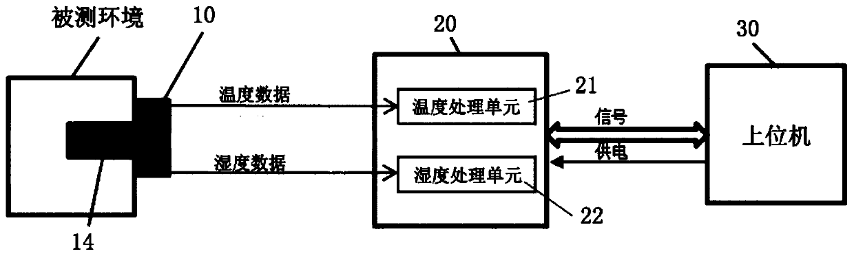
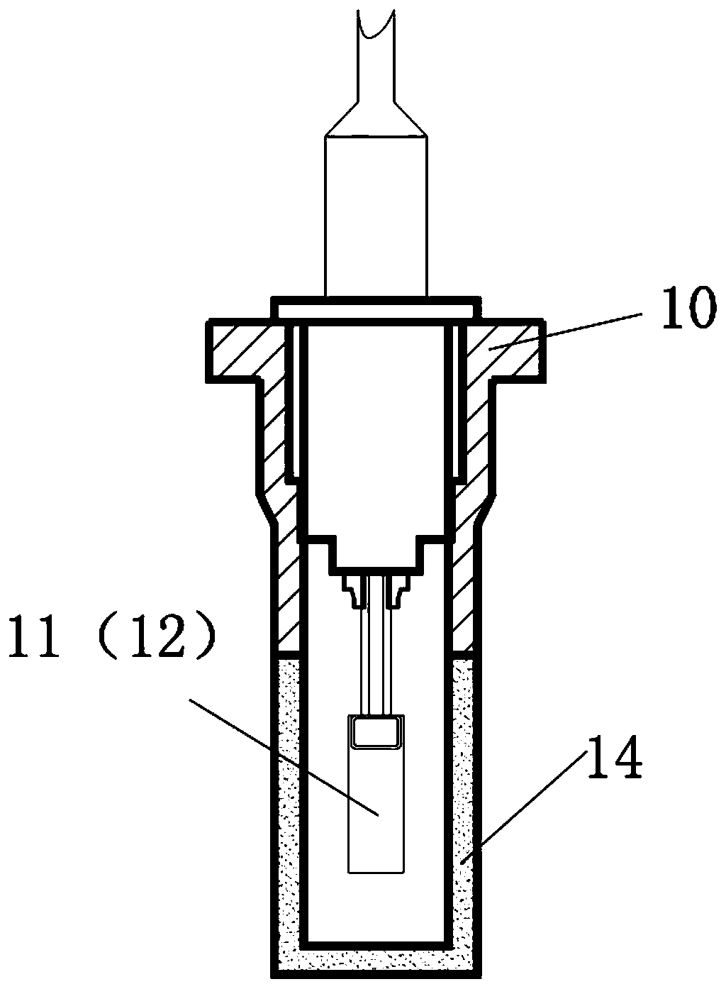
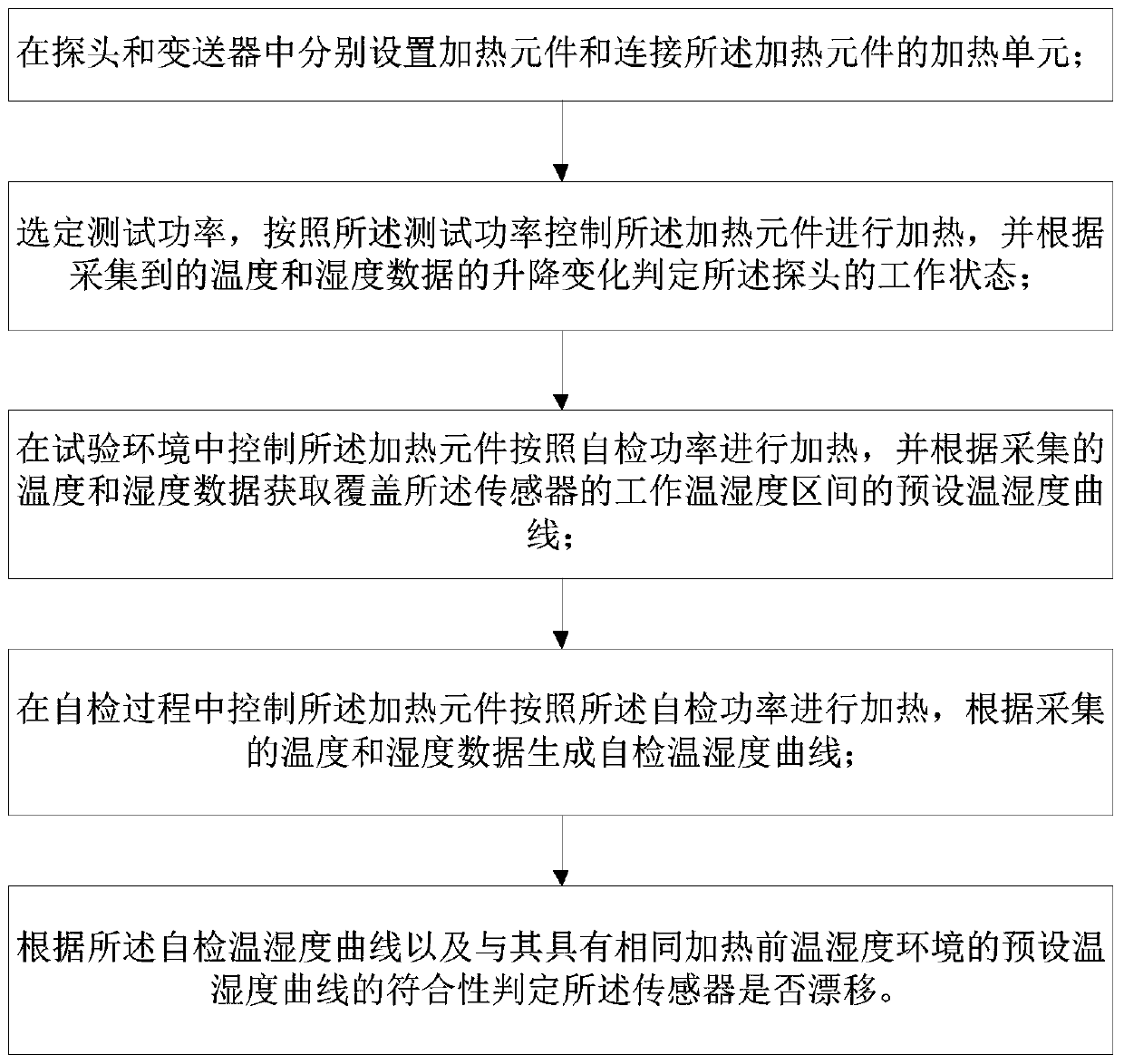
[0051] In order to solve the problem that the existing technology cannot judge and detect the real state and specific performance of the temperature and humidity sensor, the present invention aims to provide a self-checking method for the temperature and humidity sensor. Element, add a heating unit to the transmitter, when self-test is required, the space inside the probe filter will be heated after the heating unit controls the heating element to heat up, the environment in the filter will be affected, causing the temperature to rise and the humidity to drop . Therefore, it is possible to compare the temperature and humidity data collected after heating with the data before the self-test, and analyze whether the change value conforms to the ...


PUM


Abstract

The invention provides a self-test method for a temperature and humidity sensor. The self-test method includes the following steps that: a heating element and a heating unit connected with the heatingelement are respectively arranged in a probe and a transmitter; the heating element is controlled to perform heating, and the working state of the probe is judged according to the rise and fall change of collected temperature and humidity data; in a test environment, the heating element is controlled to perform heating according to self-test power, so that a preset temperature and humidity curvecovering the working temperature and humidity interval of the sensor is obtained; during a self-test process, the heating element is controlled to perform heating according to self-test power, so thata self-test temperature and humidity curve is generated; and whether the sensor drifts is judged according to the conformity of the self-test temperature and humidity curve and the preset temperatureand humidity curve which is obtained under the test environment having the same before-heating temperature and humidity environment with the self-test temperature and humidity curve. With the self-test method provided by the invention adopted, the working state and performance of the sensor can be remotely judged, the self-check problem of the temperature and humidity sensor can be solved, and good technical effects can be realized.

Description

technical field [0001] The invention relates to the technical field of automation control and instrumentation, in particular to a self-checking method of a temperature and humidity sensor. Background technique [0002] figure 1 is the structural block diagram of the existing temperature and humidity sensor, such as figure 1 As shown, the temperature and humidity sensor generally includes a probe 10, a transmitter 20 and a host computer 30. The probe 10 is responsible for sensing the measured environment, the transmitter 20 is responsible for signal processing, calculation and output, and the host computer 30 is responsible for power supply and signal transmission. to combine figure 2 As shown, the probe 10 is provided with a temperature sensitive element 11 and a humidity sensitive element 12, and is protected by a filter 14. The temperature sensitive element 11 usually adopts a thermistor RTD (such as: PT100, PT1000 or copper resistance) that is sensitive to temperature....

Claims


Application Information

Patent Timeline
Patent Type & Authority Applications(China)
IPC IPC(8): G01D18/00
Inventor 夏祖国何小波张华骆楠珂王楷王敬龚海洪张国庆周新建田骏
Owner 中广核工程有限公司
Why Eureka
Try Eureka