Double-stage air lock apparatus for ash discharge port

A technology of ash unloading device and air lock, which is applied to the separation of dispersed particles, chemical instruments and methods, and filtration of dispersed particles. Good wind performance and power saving effect

Inactive Publication Date: 2019-06-21
XIANGTAN COUNTY FUMIN SMALL SIZED TRANSPLANTER MFG PLANT
View PDF0 Cites 1 Cited by
  • Summary
  • Abstract
  • Description
  • Claims
  • Application Information

AI Technical Summary

Problems solved by technology

[0003] Using electric or pneumatic ash unloading valve, this kind of air lock device has the disadvantage that it cannot realize the air lock when unloading ash.
When unloading dust in a negative pressure state, due to opening the valve plate or running wear, the outside air leaks into the dust collector, and the dust in the dust bucket is re-absorbed to the surface of the filter bag, causing secondary adsorption and increasing the cleaning time. The number of times shortens the cleaning cycle, increases the running resistance of the dust collector, and affects the service life of the dust collector; when the dust is unloaded under positive pressure, the dust in the dust hopper of the dust collector will be ejected, causing secondary dust.
[0004] Air locking devices such as single-connected flap valve and double-connected hammer flap valve are adopted, and the valve plate cannot be completely sealed during ash discharge.
Especially when the dust collector is in the state of positive pressure operation, it is more difficult to ensure the sealing and air lock effect, and some dust-laden gas is ejected from the ash discharge port; The valve plate is tightly sucked and cannot be unloaded, and all of them are blocked in the ash hopper of the dust collector, so that the dust collector cannot operate normally.
[0005] Whether it is a single-stage electric ash unloading valve, a pneumatic flap valve, a single-connected flap valve, a double-connected hammer flap valve, etc., in addition to poor sealing and air locking effects, they all have a common disadvantage: due to dust removal There is not a lot of dust removed by the dust collector, and the dust collector is periodically cleaned. When the dust collector is not cleared, the conveying equipment below is still in operation, doing useless work and wasting a lot of electric energy

Method used


Image

  • Double-stage air lock apparatus for ash discharge port
  • Double-stage air lock apparatus for ash discharge port

Examples


Embodiment Construction

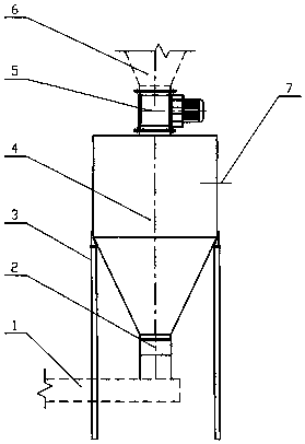
[0014] The specific embodiment of the present invention will be further described below in conjunction with accompanying drawing:

[0015] A rigid impeller feeder 5 is installed below the ash hopper 6, and the middle is sealed with a rubber gasket to realize a first-level air lock. Considering the problem that the first-level air-locking device cannot achieve complete sealing, a storage bin 4 is added below the rigid impeller feeder 5, and the middle is sealed with a rubber gasket to achieve a second-level air-locking.

[0016] The storage bin 4 is supported by the bracket 3, and the secondary ash unloading device 2 is connected below the storage bin 4.

[0017] A material level gauge 7 is arranged in the storage bin 4 .

[0018] The dust collected by the dust collector in the ash hopper 6 is first sent to the storage bin 4 through the rigid impeller feeder 5, and at this time, the secondary ash unloading device 2 and the conveying equipment 1 are both in a stopped state. Wh...


PUM


Abstract

The invention discloses a double-stage air lock apparatus for an ash discharge port. The double-stage air lock apparatus comprises an ash hopper and an ash discharge device, wherein a blade wheel feeder is installed below the ash hopper. According to the present invention, the double-stage air lock apparatus has characteristics of double-stage air lock and good air lock performance, can achieve acompletely sealed state, can ensure the optimal running effect of the dust remover, and can achieve the automated control of the dust discharge and the conveying of the dust remover, such that the conveying device achieves the functions of feeding in the presence of the material and stopping in the absence of the material, the condition that most of the current conveying devices are in the uselessoperation modes is avoided, and the purpose of electricity consumption saving is achieved.

Description

technical field [0001] The invention relates to dust removal equipment for controlling air pollution, in particular to a two-stage air lock device for the dust discharge port of the dust collector. Background technique [0002] At present, the ash unloading lock air valve of the dust collector usually adopts single-stage electric ash unloading valve, pneumatic flap valve, single flap valve, double hammer flap valve, etc. [0003] Electric or pneumatic ash unloading valves are used, but this kind of air locking device has the disadvantage that it cannot realize air locking when unloading ash. When unloading dust in a negative pressure state, due to opening the valve plate or running wear, the outside air leaks into the dust collector, and the dust in the dust bucket is re-absorbed to the surface of the filter bag, causing secondary adsorption and increasing the cleaning time. The number of times shortens the dust cleaning cycle, increases the running resistance of the dust c...

Claims


Application Information

Patent Timeline
Patent Type & Authority Applications(China)
IPC IPC(8): B01D46/42B01D46/48B01D46/02
Inventor 楚花平
Owner XIANGTAN COUNTY FUMIN SMALL SIZED TRANSPLANTER MFG PLANT
Why Eureka
Try Eureka