A Catalyst Quantitative Feeding Device
A technology of reclaiming device and catalyst, applied in the direction of powder material distribution, etc., can solve the problems of waste, catalyst waste, catalyst easy to drop, etc., and achieve the effect of avoiding waste
- Summary
- Abstract
- Description
- Claims
- Application Information
AI Technical Summary
Problems solved by technology
Method used
Image

Examples
Embodiment 1
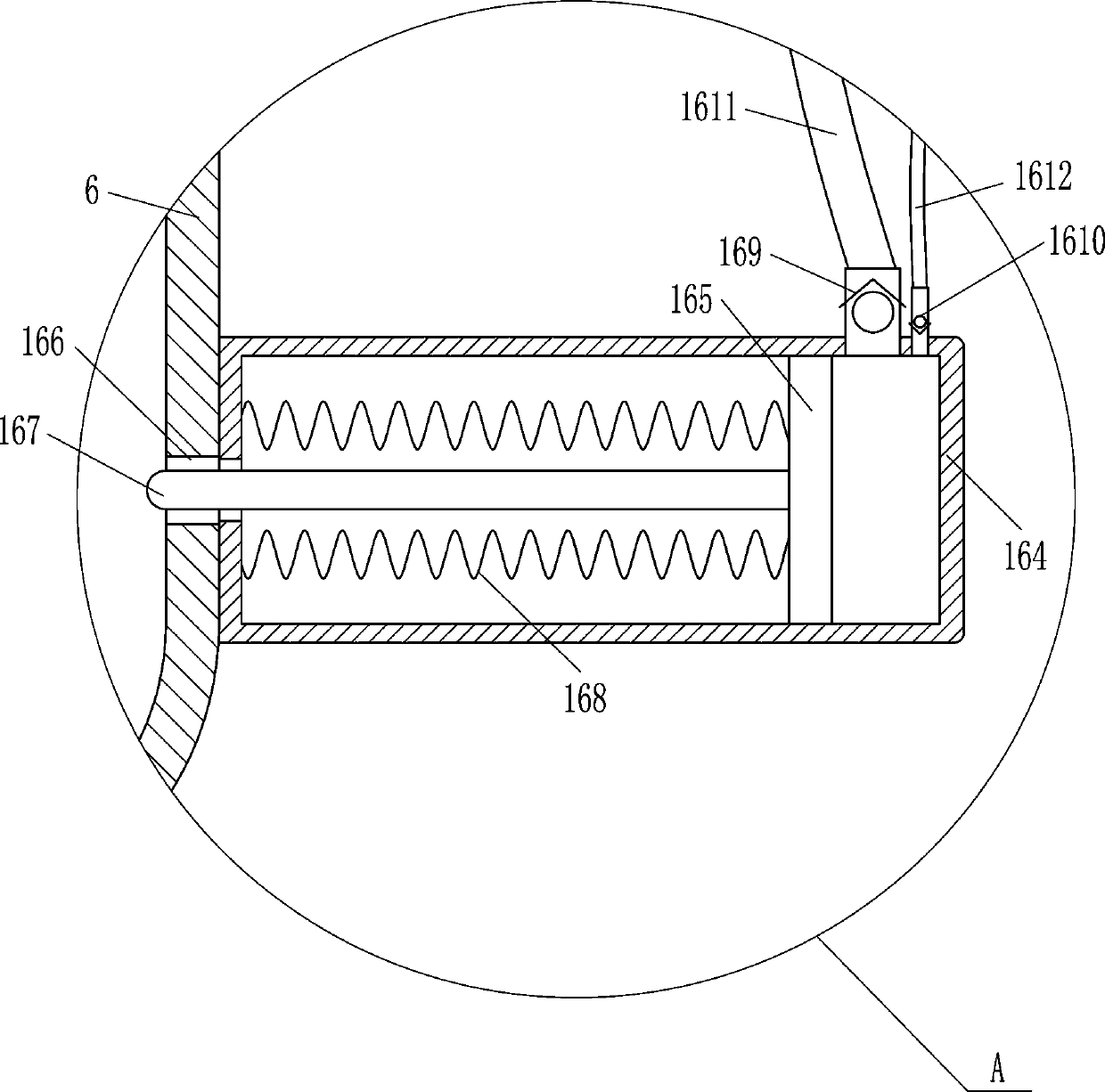
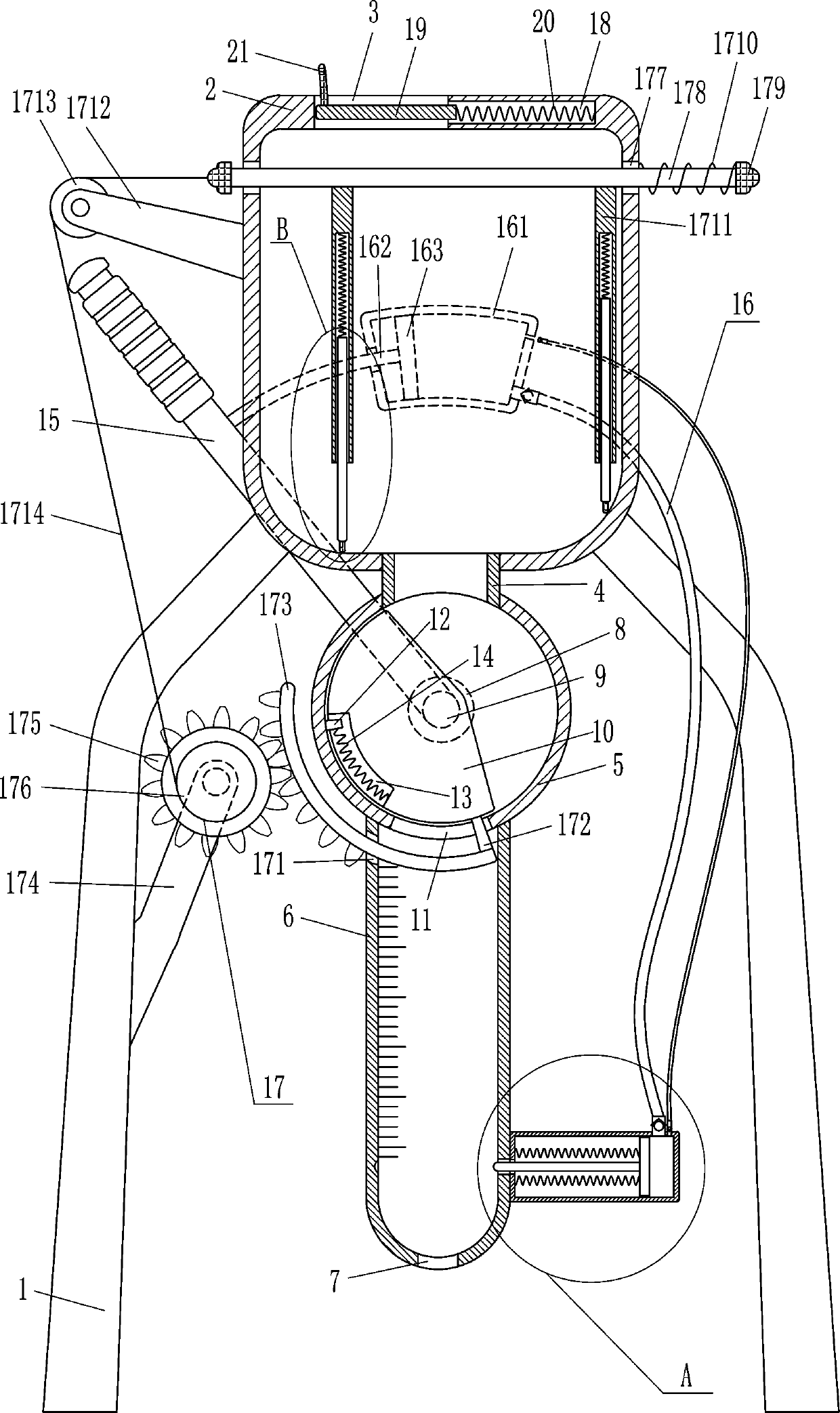
[0016] A catalyst quantitative taking device, such as Figure 1-3 As shown, it includes a leg 1, a charging box 2, a connecting pipe 4, a hollow cylinder 5, a scale transparent pipe 6, a bearing seat 8, a rotating shaft 9, a half cylinder 10, a fixed slider 12, a first spring 14, Swing bar 15 and material retaining device 16, both sides of the outer bottom of charging box 2 are fixedly connected with supporting leg 1, charging box 2 is connected with supporting leg 1 by the mode of welding connection, and charging box 2 top left side is opened with Catalyst can be added to the feed port 3, and the bottom of the charging box 2 is connected with a connecting pipe 4 through which the catalyst can pass. The connecting pipe 4 communicates with the charging box 2, and the bottom end of the connecting pipe 4 is fixed with a hollow cylinder 5. The connecting pipe 4 is connected to the hollow cylinder 5 by welding, the hollow cylinder 5 communicates with the connecting pipe 4, and the ...
Embodiment 2
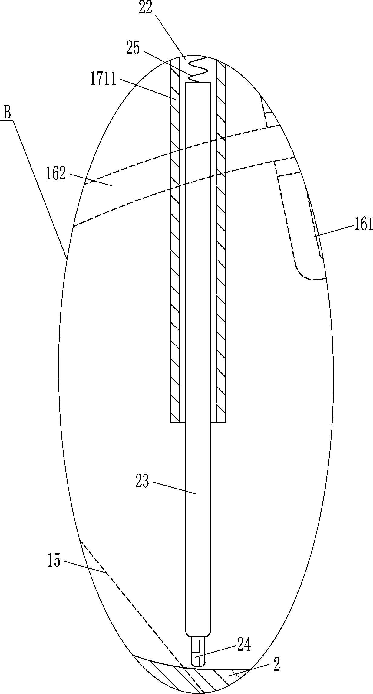
[0018] A catalyst quantitative taking device, such as Figure 1-3 As shown, it includes a leg 1, a charging box 2, a connecting pipe 4, a hollow cylinder 5, a scale transparent pipe 6, a bearing seat 8, a rotating shaft 9, a half cylinder 10, a fixed slider 12, a first spring 14, Swing bar 15 and material retaining device 16, the left and right sides of the outer bottom of charging box 2 are fixedly connected with outriggers 1, and the left side of the top of charging box 2 has a feed port 3 for catalyst to be added, and the bottom of charging box 2 Connected in the middle is a connecting pipe 4 that allows the catalyst to pass through. The connecting pipe 4 communicates with the charging box 2. The bottom end of the connecting pipe 4 is fixed with a hollow cylinder 5. The hollow cylinder 5 communicates with the connecting pipe 4. The hollow cylinder A bearing seat 8 is embedded in the center of the rear side of the body 5, and the bearing seat 8 is provided with a rotating sh...
Embodiment 3
[0021] A catalyst quantitative taking device, such as Figure 1-3 As shown, it includes a leg 1, a charging box 2, a connecting pipe 4, a hollow cylinder 5, a scale transparent pipe 6, a bearing seat 8, a rotating shaft 9, a half cylinder 10, a fixed slider 12, a first spring 14, Swing bar 15 and material retaining device 16, the left and right sides of the outer bottom of charging box 2 are fixedly connected with outriggers 1, and the left side of the top of charging box 2 has a feed port 3 for catalyst to be added, and the bottom of charging box 2 Connected in the middle is a connecting pipe 4 that allows the catalyst to pass through. The connecting pipe 4 communicates with the charging box 2. The bottom end of the connecting pipe 4 is fixed with a hollow cylinder 5. The hollow cylinder 5 communicates with the connecting pipe 4. The hollow cylinder A bearing seat 8 is embedded in the center of the rear side of the body 5, and the bearing seat 8 is provided with a rotating sh...
PUM
 Abstract
Description
Claims
Application Information
 - R&D
- Intellectual Property
- Life Sciences
- Materials
- Tech Scout
- Unparalleled Data Quality
- Higher Quality Content
- 60% Fewer Hallucinations
Browse by: Latest US Patents, China's latest patents, Technical Efficacy Thesaurus, Application Domain, Technology Topic, Popular Technical Reports.
© 2025 PatSnap. All rights reserved.Legal|Privacy policy|Modern Slavery Act Transparency Statement|Sitemap|About US| Contact US: help@patsnap.com