Supercharge Your Innovation With Domain-Expert AI Agents!

A switch cabinet moving and static contact isolation baffle safety lock and control method

A technology of isolation baffle and control method, applied in the field of switchgear safety, can solve the problems of exposure of static contacts, accidental opening, no protection, and the isolation baffle valve drive link in the lower part of the handcart room, etc. Safety, broad application prospects, and the effect of highlighting substantive features

Active Publication Date: 2021-10-01
STATE GRID SHANDONG ELECTRIC POWER COMPANY RIZHAOPOWER SUPPLY
View PDF0 Cites 0 Cited by
  • Summary
  • Abstract
  • Description
  • Claims
  • Application Information

AI Technical Summary

Problems solved by technology

[0002] In recent years, the State Grid Corporation of China has caused many personal accidents due to the operation and maintenance of the switchgear.
For example, if the current transformer CT is replaced for a switch cabinet of a substation, the secondary wiring of the current transformer CT of the switch cabinet is inside the cable room. The valve of the isolation baffle of the static contact has no protection, and the transmission link of the valve of the isolation baffle is in the lower part of the handcart room. The maintenance personnel are easy to mislead and open the valve, so that the dynamic and static contacts are exposed.

Method used


Image

  • A switch cabinet moving and static contact isolation baffle safety lock and control method
  • A switch cabinet moving and static contact isolation baffle safety lock and control method
  • A switch cabinet moving and static contact isolation baffle safety lock and control method

Examples


Embodiment 1

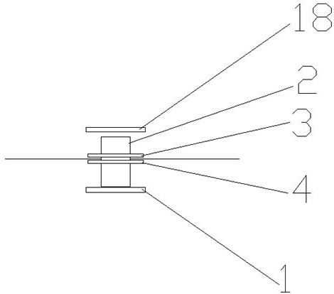
[0058] Such as figure 2 , image 3 ,and Figure 4 As shown, the present invention provides a safety lock for the isolation baffle of the movable and static contacts of the switch cabinet, comprising a first electromagnet 1, a locking ring 2, a locking ring support frame 3 and a hanging nose 4; the locking ring 2 is a circle ring shape;

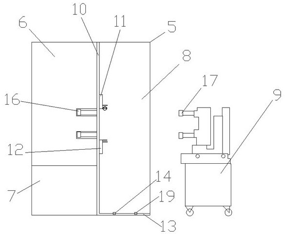
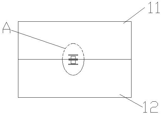
[0059] Such as figure 1 As shown, the switchgear 5 includes a busbar room 6, a cable room 7, a circuit breaker handcart room 8 and a circuit breaker handcart 9, and an isolation baffle 10 is arranged between the busbar room 6 and the circuit breaker handcart room 8 to isolate An opening is provided on the baffle plate 10, and an upper valve 11 and a lower valve 12 are provided at the opening;

[0060] A static contact box is arranged in the bus chamber 6, and a static contact 16 is arranged in the static contact box;

[0061] The circuit breaker handcart 9 is provided with a moving contact 17. When the switchgear is in normal operation, ...

Embodiment 2

[0073] In the above-mentioned embodiment 1, a second electromagnet 18 is also provided on the upper valve 11, and the second electromagnet 18 is arranged on the upper part of the locking ring 2; the second electromagnet 18 is also connected to the controller 15;

[0074] The slide rail 13 is also provided with a second travel switch 19, the distance between the second travel switch 19 and the isolation baffle 10 is greater than the distance between the first travel switch 14 and the isolation baffle 10;

[0075] The second travel switch 19 is also connected with the controller 15;

[0076] Such as Figure 5 and Figure 6 As shown, when the controller 15 receives the signal of the first travel switch 14, and then receives the signal of the second travel switch 19, it means that the circuit breaker handcart 8 moves to the outside of the switch cabinet 5, and the switch cabinet 5 is in the maintenance state, so The first electromagnet 1 is controlled to be powered on, the secon...

Embodiment 3

[0083] The present invention provides a control method based on the above-mentioned switchgear dynamic and static contact isolation baffle safety lock, including the following steps:

[0084] S1. When the switchgear is overhauled, the handcart of the circuit breaker moves along the slide rail to the direction away from the isolation baffle, the moving contact moves with the handcart of the circuit breaker, the moving and static contacts are separated, and the upper and lower valves move toward the middle until valve closed;

[0085] S2. The locking ring moves down with the locking ring support frame and the upper valve until it falls into the hanging nose;

[0086] S3. The controller receives the signal of the first travel switch, controls the first electromagnet to be powered on, and the first electromagnet attracts the locking ring to realize the locking of the valve;

[0087] S4. After the switch cabinet is overhauled, the circuit breaker handcart moves along the slide rai...


PUM


Abstract

The invention provides a safety lock and a control method for the isolation baffle of the movable and static contacts of the switch cabinet. The safety lock includes a first electromagnet, a locking ring, a supporting frame for the locking ring and a hanging nose; The compartment, the circuit breaker handcart, the isolation baffle, the upper valve and the lower valve; the locking ring support frame includes a hollow outer frame and the middle beam, and the locking ring runs through the middle beam; the locking ring support frame is arranged at the lower part of the upper valve, and Perpendicular to the upper valve; the hanging nose is set on the upper part of the lower valve corresponding to the locking ring support frame, and the shape and size of the hanging nose and the hollow outer frame of the locking ring support frame are the same; the first electromagnet is set on the hanging nose of the lower valve The lower position, and the first electromagnet is perpendicular to the lower valve; there is a slide rail at the bottom of the handcart room of the circuit breaker, and the handcart of the circuit breaker slides along the slide rail; the first travel switch is arranged on the slide rail; the first travel switch is connected with A controller, the controller is also connected with the first electromagnet; the locking ring is made of ferrous material.

Description

technical field [0001] The invention belongs to the field of switchgear safety, and in particular relates to a safety lock and a control method for a dynamic and static contact isolation baffle of a switchgear. Background technique [0002] In recent years, the State Grid Corporation of China has caused many personal accidents due to the operation and maintenance of the switchgear. For example, if the current transformer CT is replaced for a switch cabinet of a substation, the secondary wiring of the current transformer CT of the switch cabinet is inside the cable room. The valve of the static contact isolating baffle has no protection, and the transmission connecting rod of the valve of the isolating baffle is in the lower part of the handcart room. The maintenance personnel are easy to mislead and open the valve, exposing the dynamic and static contacts. [0003] This is the deficiency of the prior art. Therefore, aiming at the above-mentioned defects in the prior art, it...

Claims


Application Information

Patent Timeline
Patent Type & Authority Patents(China)
IPC IPC(8): E05B47/02E05B65/52
Inventor 王伟房克峰焦庆丽马文华殷铭泽陈淼裴丽伟王凡王薇林雨刘军张萌满阳阳
Owner STATE GRID SHANDONG ELECTRIC POWER COMPANY RIZHAOPOWER SUPPLY
Features
  • R&D
  • Intellectual Property
  • Life Sciences
  • Materials
  • Tech Scout
  • Unparalleled Data Quality
  • Higher Quality Content
  • 60% Fewer Hallucinations
Learn More