
Cutting process

A cutting process and cutting surface technology, which is used in electrical components, semiconductor/solid-state device manufacturing, circuits, etc., can solve the problems of difficult to clean EMC or SMC substrate cups, strong EMC or SMC substrates, and low production efficiency. The effect of reducing production cost, shortening time-consuming and high practicability

Pending Publication Date: 2019-06-21
XIAMEN XINDECO IOT & OPTPELECTRONICS TECH INST CO LTD
View PDF0 Cites 2 Cited by
  • Summary
  • Abstract
  • Description
  • Claims
  • Application Information

AI Technical Summary

Problems solved by technology

[0003] In the cutting process of replacing low-viscosity optical film with traditional UV film, for pre-cutting of EMC or SMC substrate, the low-viscosity optical film with low viscosity will cause flying material in cutting or cleaning, which will cause dirt in the EMC or SMC substrate cup to be difficult wash off
However, an optical film with a high viscosity will make it difficult to unload the EMC or SMC substrate due to too strong viscosity, and even cause the substrate to break during the unloading process.
In LED manufacturing, EMC or SMC substrates need a bottom film when pre-cutting. The existing bottom film is a UV film. The UV film needs to be degummed and cleaned during cutting. The process is cumbersome, the production efficiency is low, and the cost is high.

Method used


Image

  • Cutting process
  • Cutting process
  • Cutting process

Examples


Embodiment Construction

[0027] The present invention will be further described below in conjunction with the accompanying drawings and specific embodiments.

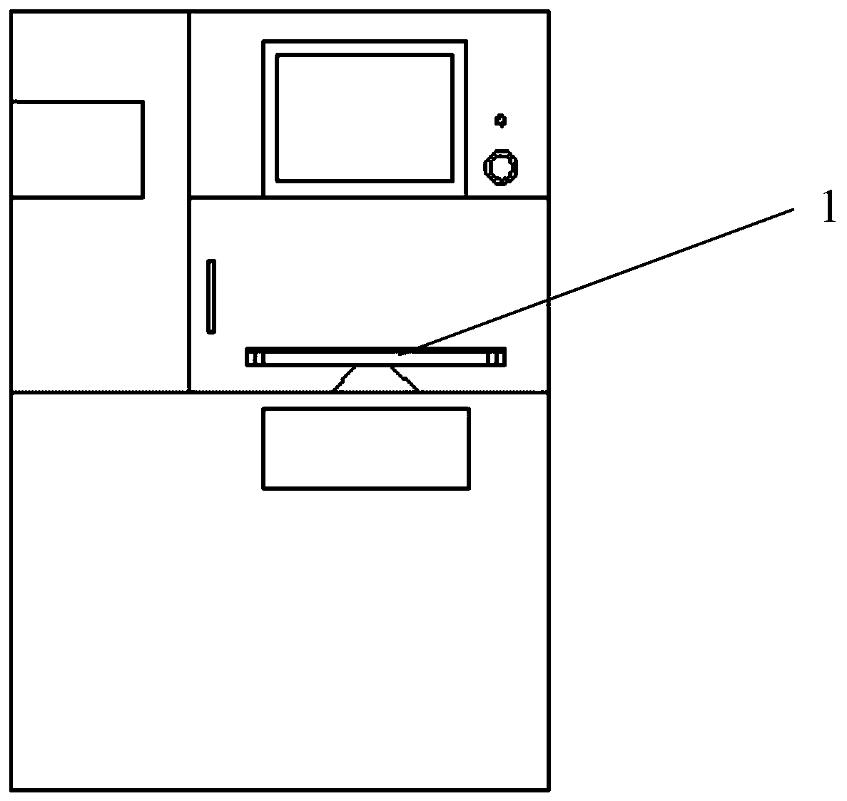
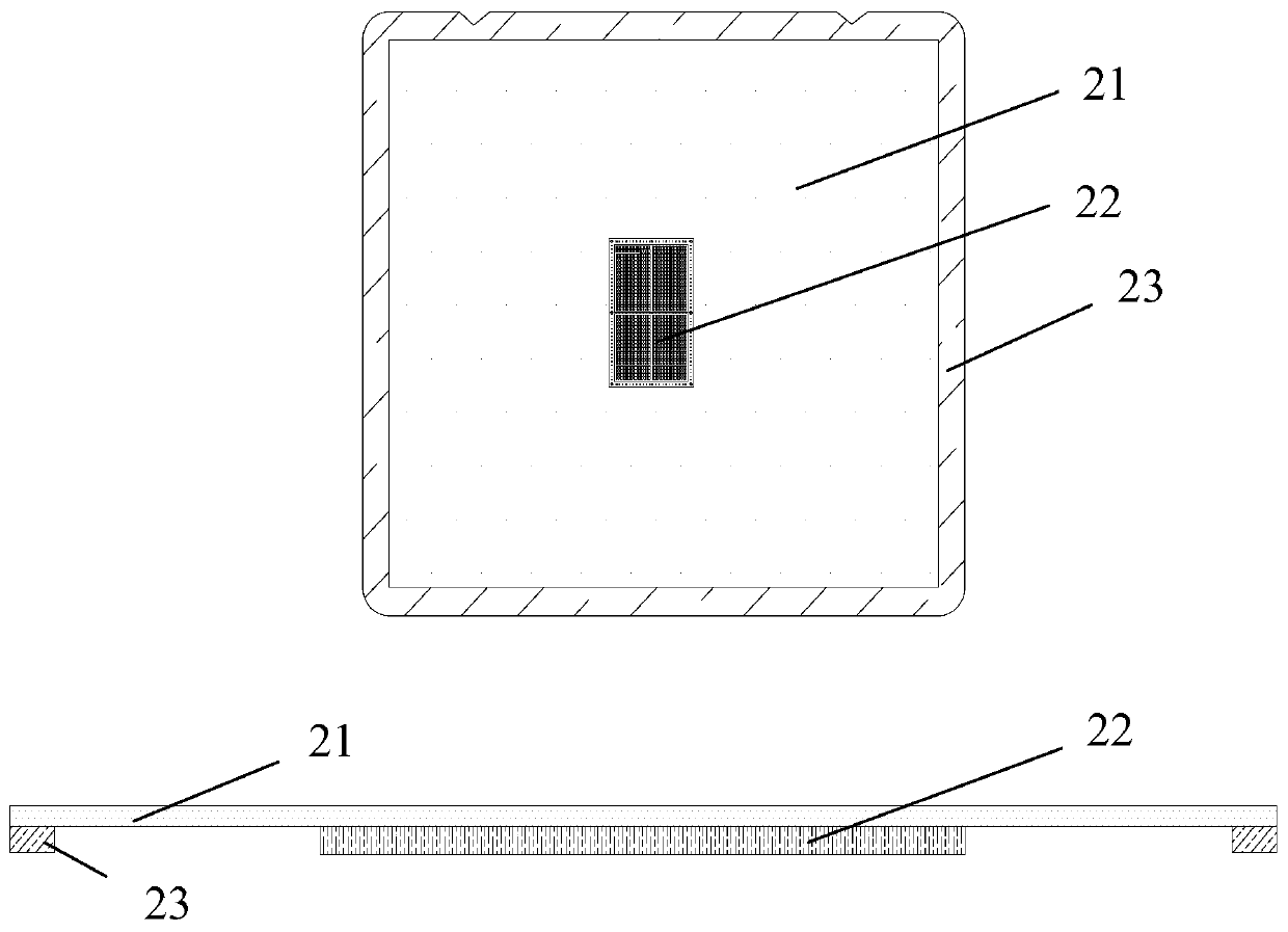
[0028] A cutting process, refer to Figures 1 to 5 , including steps:

[0029] (1) Paste at least one substrate 22 on the front middle part of the low-viscosity optical film 21; the substrate 22 includes a cutting surface, and the cutting surface of the substrate 22 faces the low-viscosity optical film 21; The surrounding edges of the optical film 21 that are not in contact with the substrate 22 are attached to the front of the low-viscosity optical film 21 to form the substrate assembly 2;

[0030] (2) Put the substrate assembly 2 into the vacuum workbench of the automatic cutting machine, the side of the low-viscosity optical film 21 pasted with the substrate 22 is facing the vacuum workbench, that is, the low-viscosity optical film 21 and the vacuum workbench are provided with Described substrate 22, there is cutting track 3 on the cutting...


PUM


Abstract

The invention provides a cutting process. The cutting process comprises the following steps: (1) adhering at least one substrate in the middle of a front of a low-viscosity optical film, wherein the substrate comprises a cutting surface, and the cutting surface of the substrate is oriented to the low-viscosity optical film; and then adhering a cutting ring on the front of the low-viscosity opticalfilm along the surrounding edge, non-contacting with the substrate, of the low-viscosity optical film, wherein one surface, adhered with the substrate, of the low-viscosity optical film is oriented to a vacuum work table, namely, the substrate is arranged at the low-viscosity optical film and the vacuum work table, and then pre-cutting the substrate by using a diamond blade; (3) after the cuttingis accomplished, blowing off the moisture and substrate chippings on the low-viscosity optical film by using an air gun, and then fixing the substrate and tearing off the low-viscosity optical film according to a diagonal track; and (4) placing the precut substrate on the vacuum work table in a material box. The substrate pre-cutting program can be simplified by applying the technical scheme, andthe production efficiency is improved.

Description

technical field [0001] The invention relates to the field of EMC or SMC substrates, and specifically refers to a cutting process. Background technique [0002] In the EMC or SMC substrate pre-cutting process, first attach the UV film with a high-viscosity glue layer to the front of the EMC or SMC substrate; Cutting machine manufacturers such as DISCO, NDS) use the vacuum suction holes on the stage to absorb the UV film; then use a high-speed rotating diamond knife to incompletely cut through the EMC or SMC substrate, and only cut off the metal leads; after cutting, Use a 365nm wavelength ultraviolet light source to irradiate the UV film with a certain dose, so that the glue layer of the UV film reduces the viscosity, so that it is easy to remove the cut EMC or SMC substrate from the UV film. The working table of the automatic cutting machine is vacuum adsorption, so the working table must be kept clean. Because the diamond blade rotates very fast, up to 3000 revolutions pe...

Claims


Application Information

Patent Timeline
Patent Type & Authority Applications(China)
IPC IPC(8): H01L21/683H01L33/00
Inventor 黄才汉魏岚吴薛平陈友三
Owner XIAMEN XINDECO IOT & OPTPELECTRONICS TECH INST CO LTD
Learn More