Chip substrate and microfluidic chip

A substrate and chip technology, applied in the field of microfluidics, can solve problems such as the inability to identify the gene type, the inability to judge the biochemistry of samples and reaction enzymes, and accurate identification.

Active Publication Date: 2021-08-24
SHANGHAI TIANMA MICRO ELECTRONICS CO LTD
View PDF8 Cites 0 Cited by
  • Summary
  • Abstract
  • Description
  • Claims
  • Application Information

AI Technical Summary

Problems solved by technology

When microfluidic technology is applied to gene detection, there are thousands of positions in high-throughput microfluidic droplets. In the prior art, microscopes or high-precision cameras cannot quickly and accurately identify which droplet participates in the reaction. , that is, it is impossible to judge the biochemical reaction between the sample and the reaction enzyme, and it is impossible to identify the gene type correspondingly

Method used


Image

  • Chip substrate and microfluidic chip
  • Chip substrate and microfluidic chip
  • Chip substrate and microfluidic chip

Examples


Embodiment Construction

[0027] Various exemplary embodiments of the present invention will now be described in detail with reference to the accompanying drawings. It should be noted that the relative arrangements of components and steps, numerical expressions and numerical values ​​set forth in these embodiments do not limit the scope of the present invention unless specifically stated otherwise.

[0028] The following description of at least one exemplary embodiment is merely illustrative in nature and in no way taken as limiting the invention, its application or uses.

[0029] Techniques, methods and devices known to those of ordinary skill in the relevant art may not be discussed in detail, but where appropriate, such techniques, methods and devices should be considered part of the description.

[0030] In all examples shown and discussed herein, any specific values ​​should be construed as exemplary only, and not as limitations. Therefore, other instances of the exemplary embodiment may have dif...


PUM


Abstract

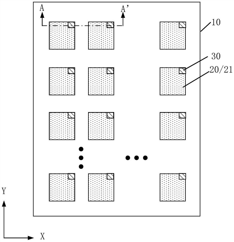
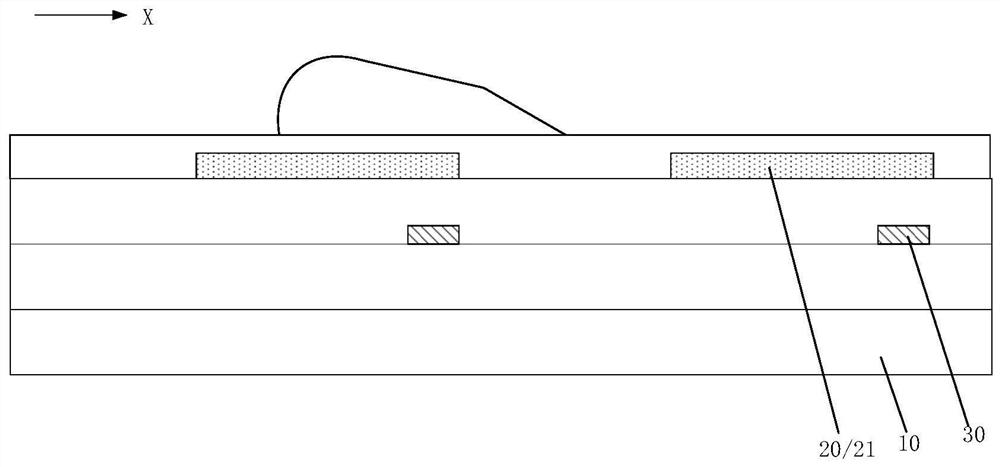
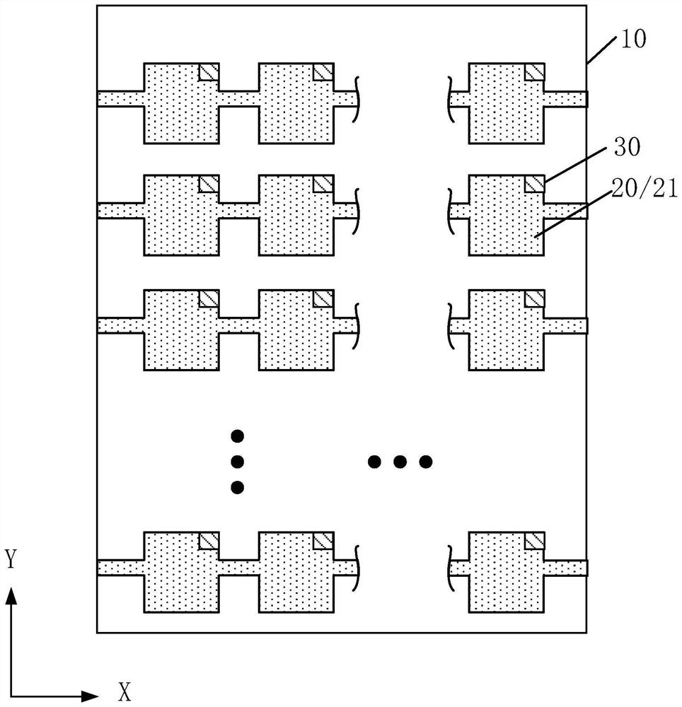
The invention discloses a chip substrate and a microfluidic chip, comprising: a base substrate and a transparent electrode layer located on one side of the base substrate, the transparent electrode layer includes a plurality of driving electrodes arranged in an array, and the driving electrodes are used to drive The movement of the droplet; a plurality of coding parts located between the base substrate and the transparent electrode layer, the coding parts and the driving electrodes are arranged in one-to-one correspondence, and the vertical projection of the coding part on the plane where the substrate is located is located at the corresponding driving electrode. Substrate In the vertical projection of the plane where the substrate is located. By will. The invention can quickly and accurately determine the position of the droplet.

Description

technical field [0001] The invention relates to the field of microfluidics, and more specifically, to a chip substrate and a microfluidics chip. Background technique [0002] Micro-fluidic technology is a technology whose main feature is the manipulation of fluid in the micron-scale space. This technology has intersected with various disciplines such as chemistry, biology, engineering and physics, showing a wide range of application prospects. [0003] At present, in the process of controlling the flow of micro-droplets using microfluidic technology, it is necessary to position the micro-droplets. Since the size of the micro-droplets is at the micron level, a microscope or a high-precision camera is used to determine the position of the micro-droplets. When microfluidic technology is applied to gene detection, there are thousands of positions in high-throughput microfluidic droplets. In the prior art, microscopes or high-precision cameras cannot quickly and accurately iden...

Claims


Application Information

Patent Timeline
Patent Type & Authority Patents(China)
IPC IPC(8): B01L3/00
Inventor 林柏全许祖钊席克瑞李小和秦锋刘金娥
Owner SHANGHAI TIANMA MICRO ELECTRONICS CO LTD
Why Eureka
Try Eureka