
Diaphragm for diaphragm valve and manufacturing method thereof

A diaphragm valve and diaphragm technology, applied in the field of diaphragms for diaphragm valves and their manufacturing, can solve the problems of huge manufacturing difficulty and limited work performance, etc.

Inactive Publication Date: 2019-06-25
塞德流量控制有限责任公司
View PDF14 Cites 2 Cited by
  • Summary
  • Abstract
  • Description
  • Claims
  • Application Information

AI Technical Summary

Problems solved by technology

[0012] In general, it can be established that the currently known reinforced membranes have a high strength due to the reinforcement layer, but this is accompanied by limited performance and great manufacturing difficulties

Method used


Image

  • Diaphragm for diaphragm valve and manufacturing method thereof
  • Diaphragm for diaphragm valve and manufacturing method thereof
  • Diaphragm for diaphragm valve and manufacturing method thereof

Examples


Embodiment Construction

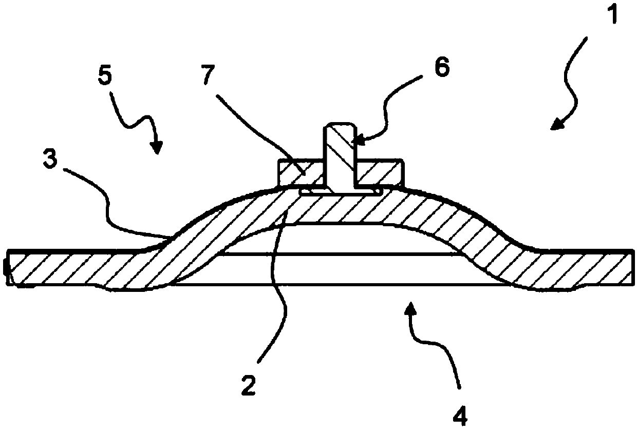
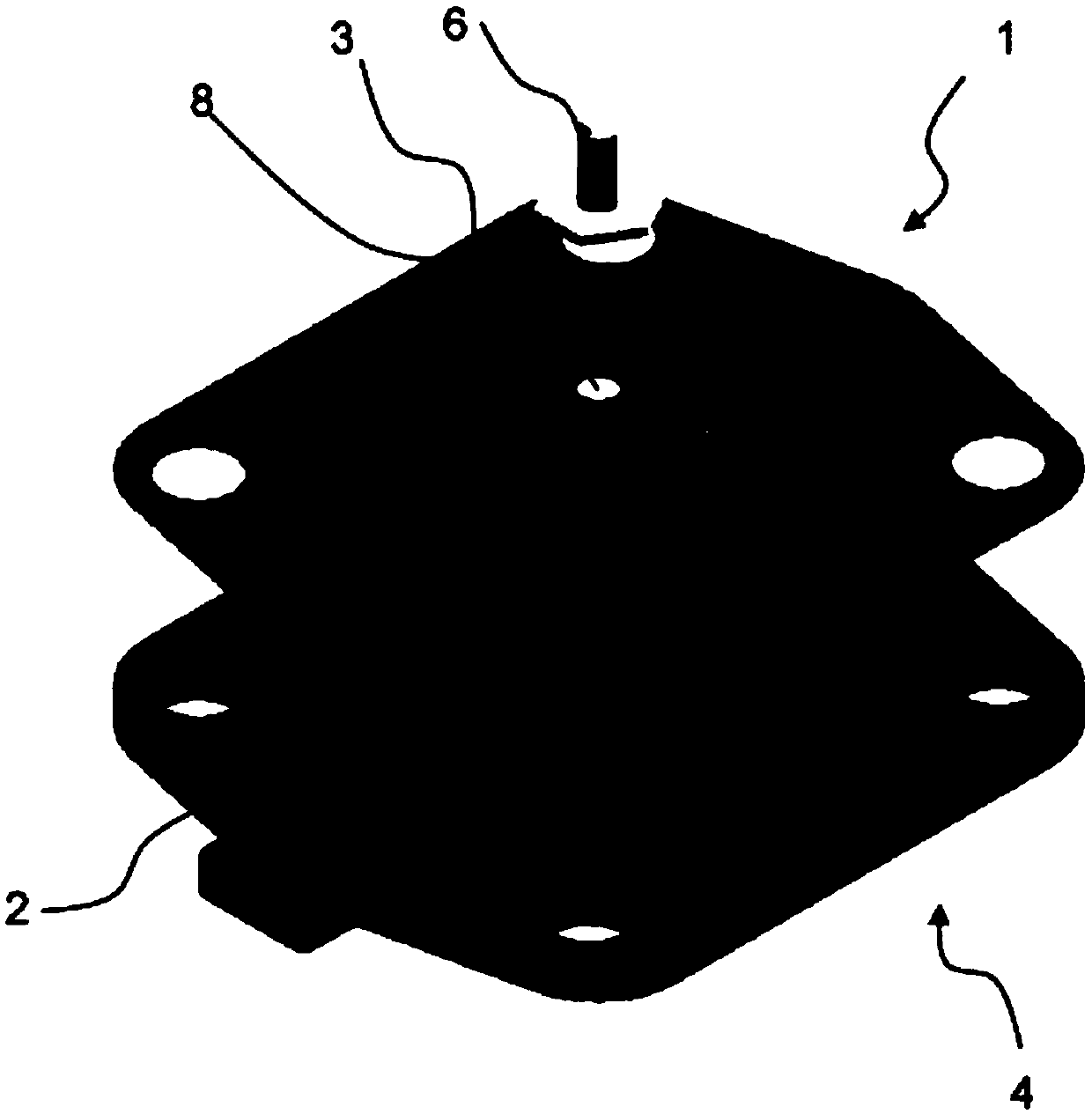
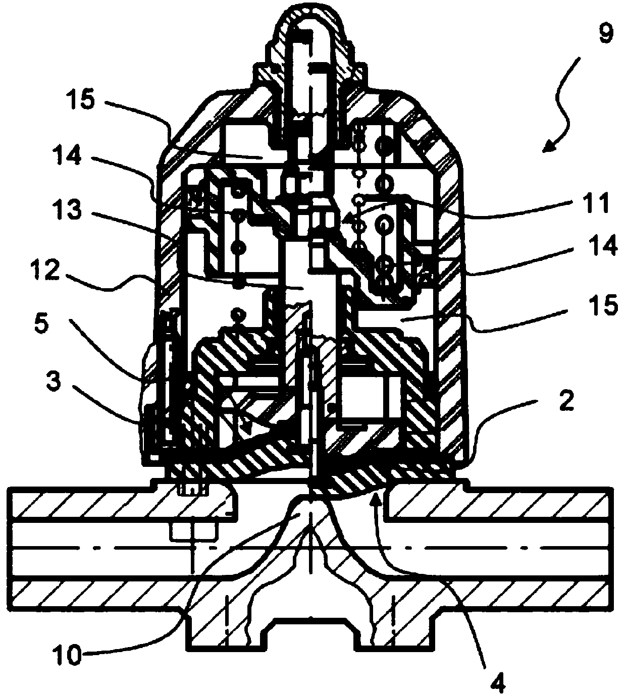
[0039] figure 1 Shown is a membrane 1 comprising a bell-shaped body 2 and a reinforcement area 3 applied to the body 2 . The bottom side of the membrane 1 is the side 4 facing the medium; the top side of the membrane 1 is the side 5 facing away from the medium. On the side 5 of the membrane 1 facing away from the medium, a force transmission component 6 is embedded in the body 2 in such a way that the reinforcement region 3 is also connected to the force transmission component 6 . The force transmission member 6 is used to direct the diaphragm 1 towards the image 3 The valve seat 10 shown below the force transmission member 6 moves and moves away. In order to transmit the force as uniformly as possible to the diaphragm 1 , the force transmission component is partially surrounded by elastomer projections 7 . In this region, the membrane 1 is three-layered, since the reinforcement region 3 extends over the entire surface of the body 1 of the membrane 1 on the side 5 facing a...


PUM


Abstract

The invention relates to a diaphragm (1) used for a diaphragm valve (9) and comprising a body (2) formed by an elastomer. The body (2) has a side (4) facing a medium and a side (5) far away from the medium. A force transmission member (6) for fixing a valve stem driver (11) of the diaphragm valve (9) is arranged on the side (5), far away from the medium, of the body (2). The body (2) is also provided with a reinforcement region (3), wherein the reinforcement region (3) is arranged on the outer side of the body (2) and is arranged on the side (5), far away from the medium, of the body.

Description

technical field [0001] The invention relates to a diaphragm for a diaphragm valve comprising a body made of elastomer, wherein the body has a side facing the medium and a side facing away from the medium, wherein on the body there is a On one side there is a force transmission member for fixing the valve stem for the diaphragm valve, and the body has a reinforcement area. The invention also relates to a method of manufacturing such a membrane. Background technique [0002] This type of diaphragm is a standard component in diaphragm valves, which are used in process technology and system engineering for conveying any medium in pipelines. The operating principle of the diaphragm is generally based on the provision of an elastically deformable wall for changing the flow cross section in the region of the valve seat. For this purpose, the elastic diaphragm is moved towards or away from the valve seat. [0003] DE 20 2014 103 142 U1 discloses a diaphragm valve comprising a dia...

Claims


Application Information

Patent Timeline
Patent Type & Authority Applications(China)
IPC IPC(8): B29C65/02B29C35/00F16K7/12
Inventor 瓦伦丁·马尔乌韦·鲁奇
Owner 塞德流量控制有限责任公司
Learn More