

Multifunctional floor drainer
A drainer and multi-functional technology, applied to drainage structures, waterway systems, water supply devices, etc., can solve problems such as sudden flushing of the falling water head, affecting daily work and rest, and failure to achieve economic benefits
- Summary
- Abstract
- Description
- Claims
- Application Information
AI Technical Summary
Problems solved by technology
Method used
Image

Examples
Embodiment Construction
[0040] In order to achieve the above-mentioned purpose and effect, the technical means and structure adopted by the present invention, the accompanying drawings illustrate in detail its features and functions as follows with regard to preferred embodiments of the present invention, so as to fully understand.
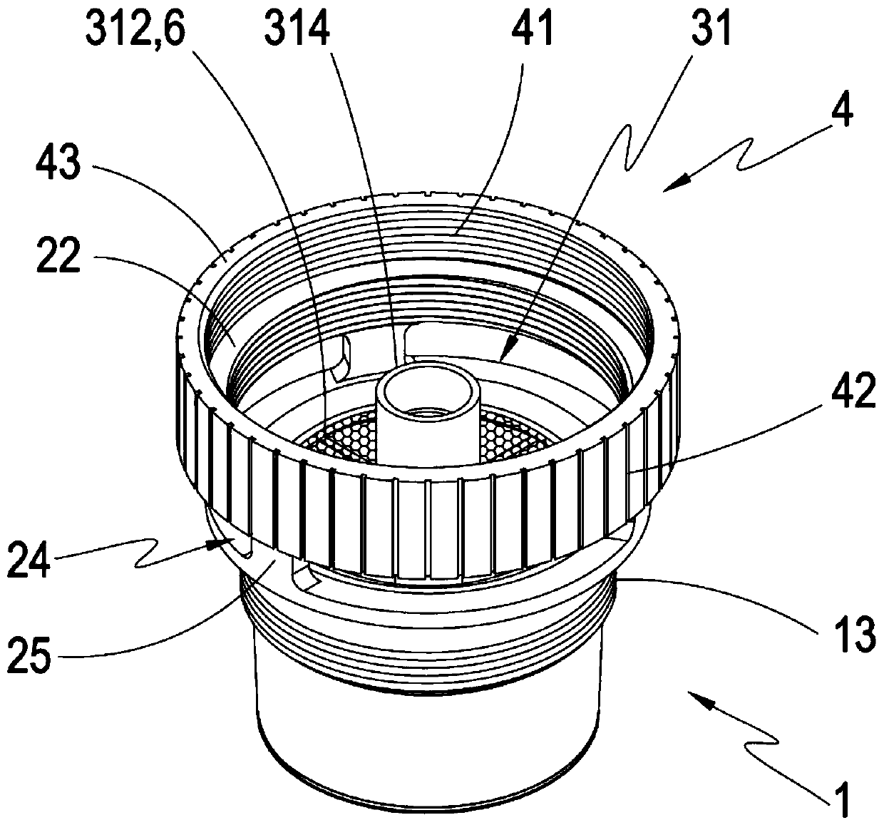
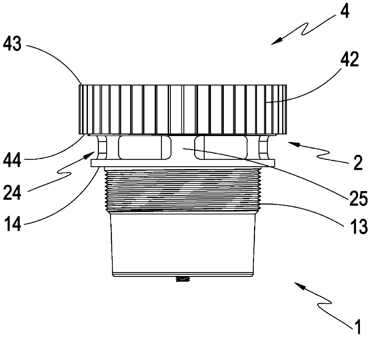
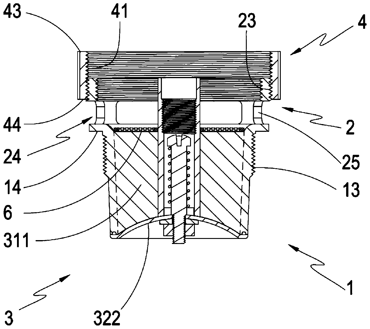
[0041] see Figures 1 to 7 As shown, it can be clearly seen from the figure that the present invention includes a drainer body 1, an extension body 2 at the upper end of the body, at least one automatic anti-odor backstop device 3, and at least one control switch 4, wherein the drainer body 1 is provided with At least one water outlet part 11 at the lower end of the body, at least one body support part 12 at the side of the water outlet part 11 at the lower end of the body, and at least one body joint part 13 at the side of the body support part 12, and the drain body 1 is combined with the body At least one integral support part 14 of the drainer is provided on the side...
PUM
 Abstract
Description
Claims
Application Information