Flexible light emitting strip

A light-emitting strip and flexible technology, applied in the field of flexible light-emitting strips, can solve the problems of cumbersome procedures and joints of strip-shaped decorative lights, and achieve the effect of the overall color unchanged

Inactive Publication Date: 2019-06-25
陕西海嵘工程项目管理有限公司
View PDF0 Cites 0 Cited by
  • Summary
  • Abstract
  • Description
  • Claims
  • Application Information

AI Technical Summary

Problems solved by technology

[0010] The present invention aims to provide a solution to the cumbersome process and seams of making strip decorative lights, which realizes the installation as simple as a light tube and achieves better quality and appearance than traditional crafts.

Method used


Image

  • Flexible light emitting strip
  • Flexible light emitting strip
  • Flexible light emitting strip

Examples


Embodiment 1

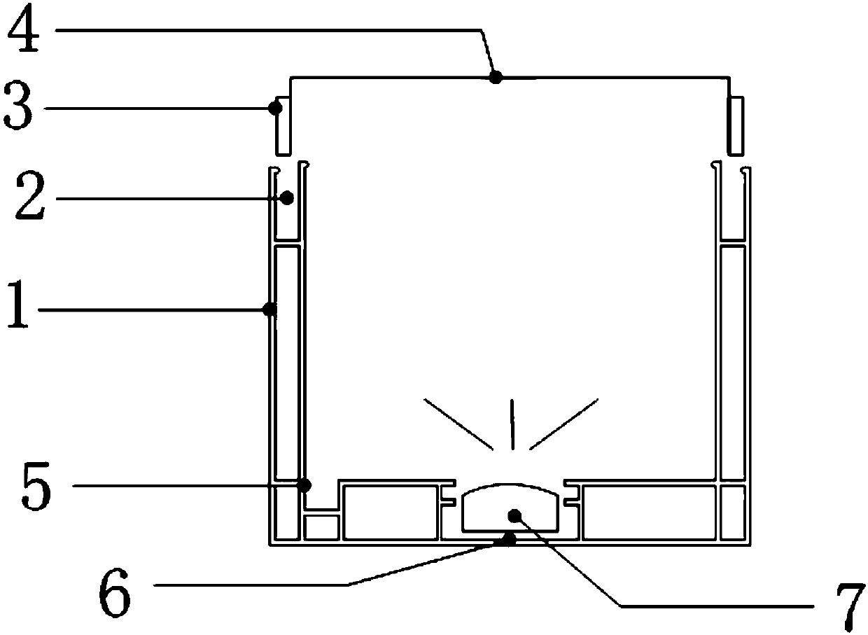
[0027] Embodiment 1, the present embodiment is attached figure 1 As shown, it is also the embodiment scheme mentioned in the claims of the present invention, the sticky rod fixing groove 2 and the sticky rod 3 are in-line, which is convenient and quick.

Embodiment 2

[0028] Embodiment 2, the present embodiment is attached Figure 4 As shown, the sticky rod 3 is changed into a hook shape, so that it is not easy to fall off after being inserted into the sticky rod fixing groove 2, and is stable and reliable.

Embodiment 3

[0029] Embodiment 3, this embodiment is attached Figure 5 As shown, the sticking rod 3 is directly arranged inside the sticking rod fixing groove 2 , and during installation, the flexible board 4 can be inserted into the gap inside the sticking rod 3 using a tool.


PUM


Abstract

The invention provides a flexible light emitting strip. The flexible light emitting strip comprises a fixing structure, a flexible plate and a light emitting diode, and is characterized in that the fixing structure is internally provided with a mounting die, the mounting die is internally provided with the light emitting diode, and the upper end of the fixing structure is provided with the flexible plate; the two ends of the flexible plate are provided with sticking rods, the upper end of the fixing structure is provided with two sticking rod fixing grooves, the inner portion of the fixing structure is also provided with main and sub clamping seats, and the sticking rods are arranged in the sticking rod fixing grooves. The flexible light emitting strip has the advantages that multiple light emitting faces are arranged and seamlessly connected with one another and can be extended continuously, the light is gentle, and the whole flexible light emitting strip is flat and beautiful; the installation does not need a complicated process, and is simple and convenient.

Description

technical field [0001] The invention relates to the field of decoration, in particular to a flexible light strip. Background technique [0002] At present, to decorate a strip-shaped luminous decorative object requires three types of work, and the manufacturing process is very complicated. Its production process is as follows: [0003] 1. The woodworker uses a chainsaw to cut out three boards and nail them into a wooden groove; [0004] 2. The woodworker uses a chainsaw to cut out small wooden strips of relative size, and nails them on both sides of the wooden groove (for final fixing of the acrylic board); [0005] 3. Painters apply glue to the joints of the small wooden strips and wooden grooves, paste explosion-proof paper strips, and wait for five hours; [0006] 4. Wait 20 hours for the first batch of putty powder, and then wait 20 hours for the second batch of putty powder, and then paint the wall twice; [0007] 5. The electrician installs the light source, fixes ...

Claims


Application Information

Patent Timeline
Patent Type & Authority Applications(China)
IPC IPC(8): F21S4/24F21V19/00F21V23/06F21Y115/10
Inventor 张毅辉
Owner 陕西海嵘工程项目管理有限公司
Why Eureka
Try Eureka