Wind power generation unloading circuit and unloading control method

A control method and unloading circuit technology, applied to battery circuit devices, circuit devices, collectors, etc., can solve problems such as reducing wind energy utilization rate and battery charging, and achieve the goals of protecting electrical equipment, system stability, and improving wind energy utilization rate Effect

Active Publication Date: 2021-04-06
HEFEI WIN POWER
View PDF7 Cites 0 Cited by
  • Summary
  • Abstract
  • Description
  • Claims
  • Application Information

AI Technical Summary

Problems solved by technology

However, this method cannot charge the battery during unloading, which reduces the utilization rate of wind energy

Method used


Image

  • Wind power generation unloading circuit and unloading control method
  • Wind power generation unloading circuit and unloading control method
  • Wind power generation unloading circuit and unloading control method

Examples


Embodiment 1

[0055] The wind power generation unloading control method provided by the present invention is suitable for a power generation system with a wind power generation unloading circuit, such as a pure wind power generation system or a wind-solar hybrid power generation system. Among them, the unloading circuit of wind power generation does not use an unloading resistor for current limiting, or has an unloading resistor with a small resistance value. The small unloading resistor resistance mentioned here means that the resistance is not enough to Limiting the current of the wind turbine may still cause damage to the wind turbine or the dump switch tube.

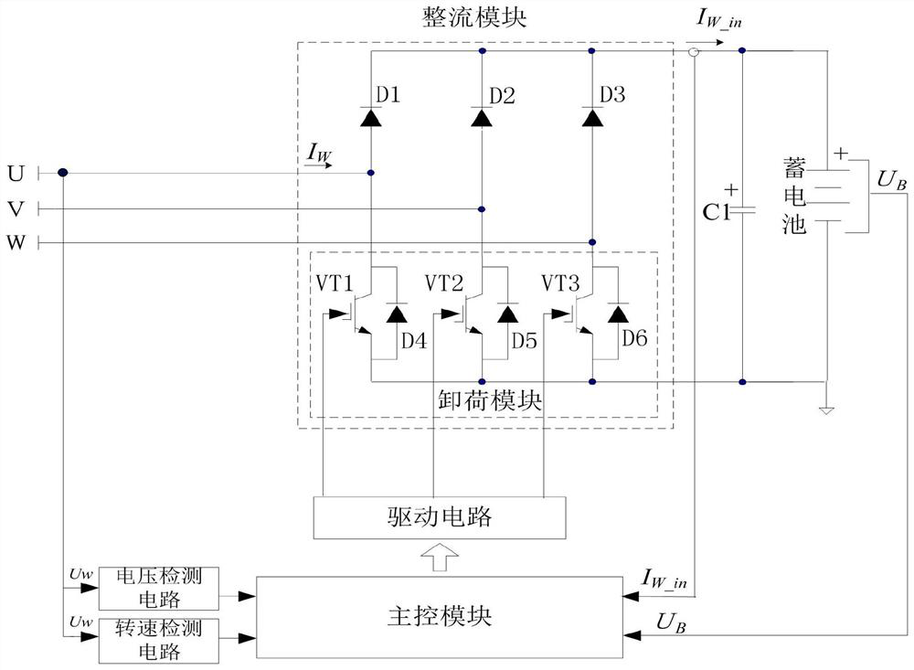
[0056] Such as figure 1 As shown, it is a block diagram of the wind power generation unloading circuit applicable to the present invention in a specific embodiment in Embodiment 1, a wind power generation unloading circuit, including a main control module, a rectifier module, an unloading module and a battery, wind power The thre...

Embodiment 2

[0097] Different from Embodiment 1 of the present invention is:

[0098] The unloading circuit for wind power generation provided by Embodiment 2 of the present invention further includes: for converting the output voltage U of the wind power generator W and battery voltage U B Matching boost module or step-down module or buck-boost module to increase the range of available wind speed and further improve the utilization rate of wind energy. Such as Figure 8 As shown, it is a structural diagram of a wind power unloading control circuit with a boost module, wherein the boost module includes an inductor L1 and a field effect transistor VT4, one end of the inductor L1 is connected to the negative pole of the diode D3, and the other end is respectively connected to the One end of the filter capacitor C1 and the drain of the field effect transistor VT4, and the source of the field effect transistor VT4 is connected to the other end of the filter capacitor C1.

[0099] It should ...

Embodiment 3

[0101] Different from Embodiment 1 of the present invention is:

[0102] Embodiment 3 of the present invention provides a wind power generation unloading circuit different from Embodiment 1 of the present invention, such as Figure 9 As shown, the rectifier module of the unloading circuit for wind power generation is a three-phase full-bridge uncontrolled rectifier circuit composed of six diodes, the unloading module is a field effect transistor VT5, and the three-phase full-bridge uncontrolled rectifier circuit The negative electrodes of the three diodes of the upper bridge arm are connected to the drain of the field effect transistor VT5, and the anodes of the three diodes of the lower bridge arm in the three-phase full bridge uncontrolled rectification circuit are connected to the source of the field effect transistor VT5 , the gate of the field effect transistor VT5 is connected to the signal output terminal of the main control module through the driving circuit, and the t...


PUM


Abstract

The invention discloses a wind power generation unloading control method. The method includes: judging whether the unloading condition is met, and when the unloading condition is met, controlling the unloading switch tube to conduct intermittently; output current, when the output current of the wind power generator exceeds the set threshold, the main control module controls the unload switch tube to be continuously turned on within the first preset time. The invention also provides a wind power generation unloading control circuit. The invention has the advantages of charging the storage battery while unloading, improving the utilization rate of wind energy, reducing the on-off frequency of the unloading switch tube, reducing switching losses, and effectively protecting wind power generators and other electrical equipment; the unloading provided by the invention The control method can also be extended to the wind-solar hybrid power generation system to realize the floating charge control of the battery by photovoltaics.

Description

technical field [0001] The invention relates to the technical field of wind power generation, and more particularly to a wind power generation unloading circuit and an unloading control method. Background technique [0002] Wind power refers to converting the kinetic energy of wind into electrical energy. Wind energy is a clean and pollution-free renewable energy source. The use of wind power to generate electricity is very environmentally friendly and has a huge wind energy reserve, so it is increasingly valued by countries all over the world. [0003] The wind power generation system stores electric energy in the battery during operation. When the battery is close to saturation, the excess electric energy needs to be converted into heat through the unloading circuit and released. For an unloading circuit that does not use an unloading resistor for current limiting, or that has a small resistance value, the following two methods are often used in the prior art for unloadi...

Claims


Application Information

Patent Timeline
Patent Type & Authority Patents(China)
IPC IPC(8): H02J7/00H02J7/32
Inventor 张为民周一晨
Owner HEFEI WIN POWER
Why Eureka
Try Eureka