Card connector

A technology of card connector and card ejection mechanism, which is applied in the direction of connection, parts of connection device, device for preventing wrong connection, etc. It can solve the problems of damage to other parts of the push rod, inconvenient use, and easy shaking of the push rod, etc. Achieve the effect of strong structural stability and convenient use

Pending Publication Date: 2019-06-28
KUNSHAN JIAHUA ELECTRONICS
View PDF12 Cites 9 Cited by
  • Summary
  • Abstract
  • Description
  • Claims
  • Application Information

AI Technical Summary

Problems solved by technology

However, due to the lack of strong support for the lateral direction of the push rod by the components in the groove, the push rod is prone to shaking, and the shaking push rod may hit and damage other components, resulting in the overall structure of the electronic card connector. Poor stability
When the tray is inserted in reverse, the tray will hit the insulating body and conductive terminals, which will easily cause damage to the electronic card connector
In addition, although the tray is provided with three card slots, since the corresponding three sets of conductive terminals are located on the same plane, the electronic card connector can only use two electronic cards at the same time, which is inconvenient to use

Method used


Image

  • Card connector
  • Card connector
  • Card connector

Examples


Embodiment Construction

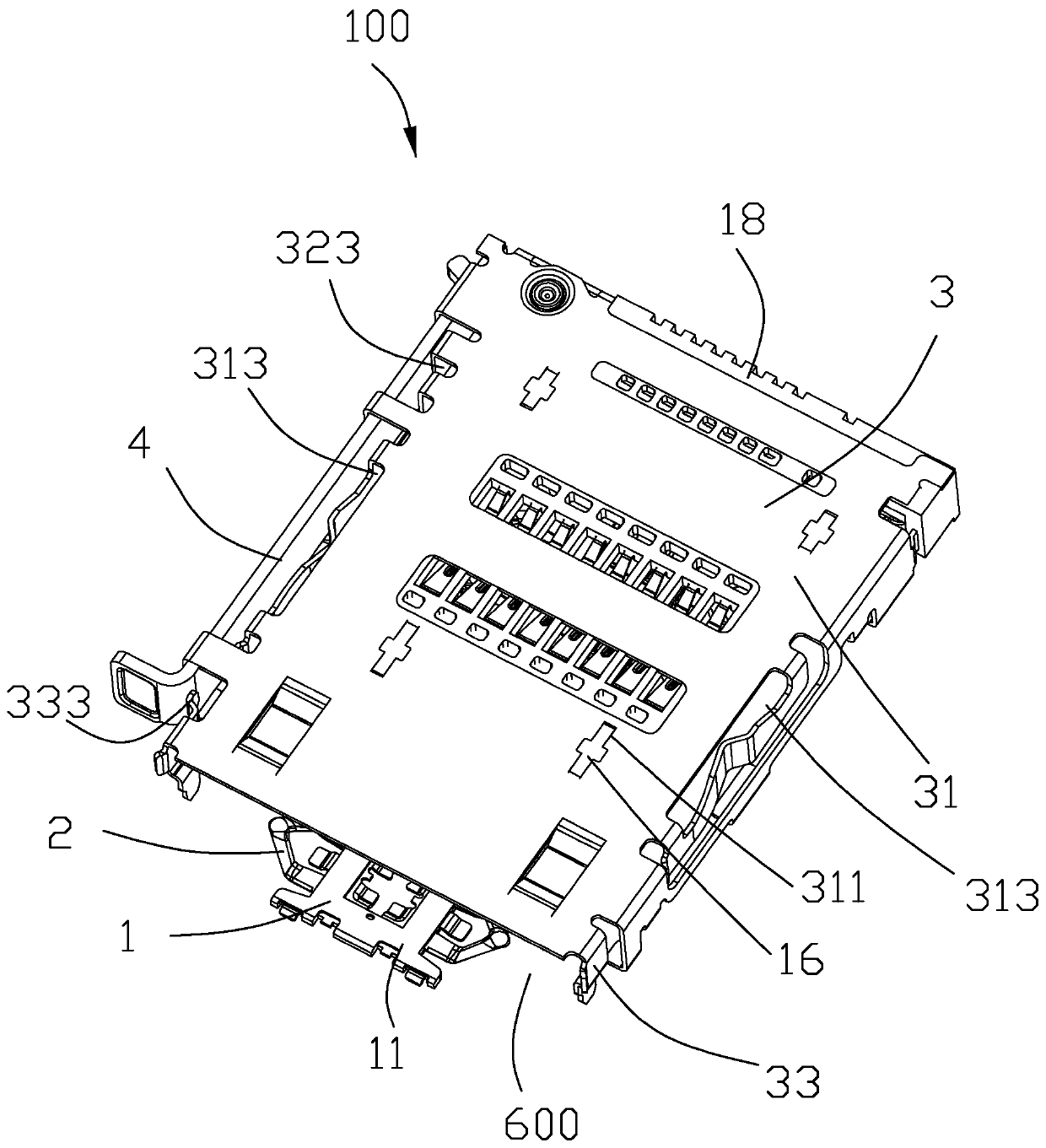
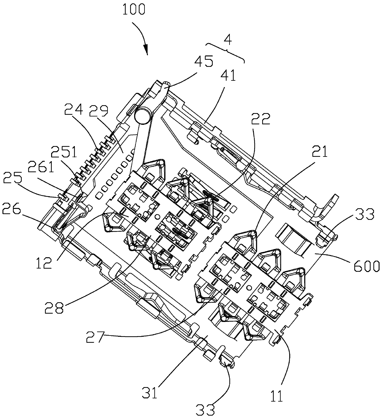
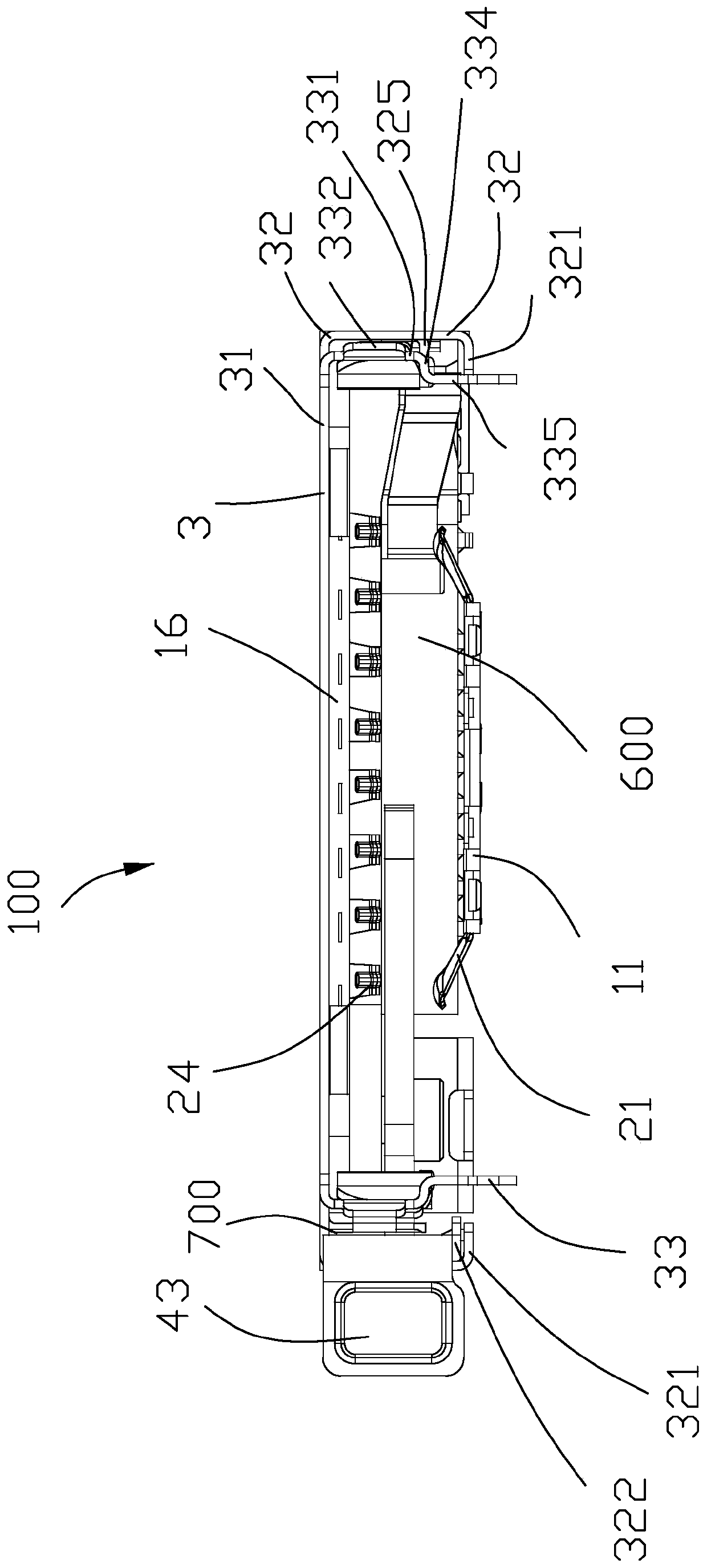
[0071] Below, will combine Figure 1 to Figure 12 The specific implementation manner of the card connector 100 of the present invention is introduced. The description of the direction of the card connector 100 in the present invention is all based on figure 1 shall prevail, in figure 1 Define the card connector 100 as the front end for the insertion of a card holder 5 that carries an electronic card, the insertion direction of the card holder 5 is the front-to-back direction, the up-down direction perpendicular to the front-to-back direction and perpendicular to the front-to-back direction and the front-to-back direction respectively. The horizontal direction of the up and down direction.

[0072] Please refer to Figure 1 to Figure 9 As shown, the present invention provides a card connector 100 installed on a circuit board (not shown). The card connector 100 includes an insulating body 1 , a plurality of conductive terminals 2 holding the insulating body 1 , a shielding c...


PUM


Abstract

The invention provides a card connector. The card connector comprises an insulating body, a plurality of conductive terminals, a shielding shell and a card withdrawing mechanism. Each conductive terminal comprises a holding part held on the insulating body, a contact part extending out of the insulating body from the holding part, and a welding part. The shielding shell forms an accommodating space. The shielding shell comprises a top plate and two side plates extending downwards from the two sides of the top plate. The card withdrawing mechanism is located in the accommodating space and abutsagainst one of the two side plates. The card withdrawing mechanism comprises a push rod and a driving part linked with the push rod. The shielding shell further comprises a fool-proof part formed byextending downwards from the side edge of the side, close to the card withdrawing mechanism, of the top plate. The fool-proof part comprises an elastic supporting part formed by extending backwards from the edge of the rear end of the fool-proof part. The elastic supporting part transversely supports the inner side surface of the push rod so as to prevent the push rod from shaking. The structuralstability is improved.

Description

【Technical field】 [0001] The invention relates to a card connector, in particular to a card connector with strong structural stability. 【Background technique】 [0002] Referring to the patent application No. CN105490074A disclosed in China, an electronic card connector is disclosed, which includes an insulating body, three sets of conductive terminals fixed on the insulating body, and a card ejection mechanism. The push rod of the card ejection mechanism is accommodated in a groove Move back and forth. However, due to the lack of strong support for the lateral direction of the push rod by the components in the groove, the push rod is prone to shaking, and the shaking push rod may hit and damage other components, resulting in the overall structure of the electronic card connector. Less stable. When the tray is inserted backwards, the tray will collide with the insulating body and the conductive terminals, easily causing damage to the electronic card connector. In addition,...

Claims


Application Information

Patent Timeline
Patent Type & Authority Applications(China)
IPC IPC(8): H01R12/71H01R13/64H01R13/24H01R13/502H01R13/629H01R13/633H01R27/00
Inventor 李风相
Owner KUNSHAN JIAHUA ELECTRONICS
Why Eureka
Try Eureka